
2 layers142 × 58 mm
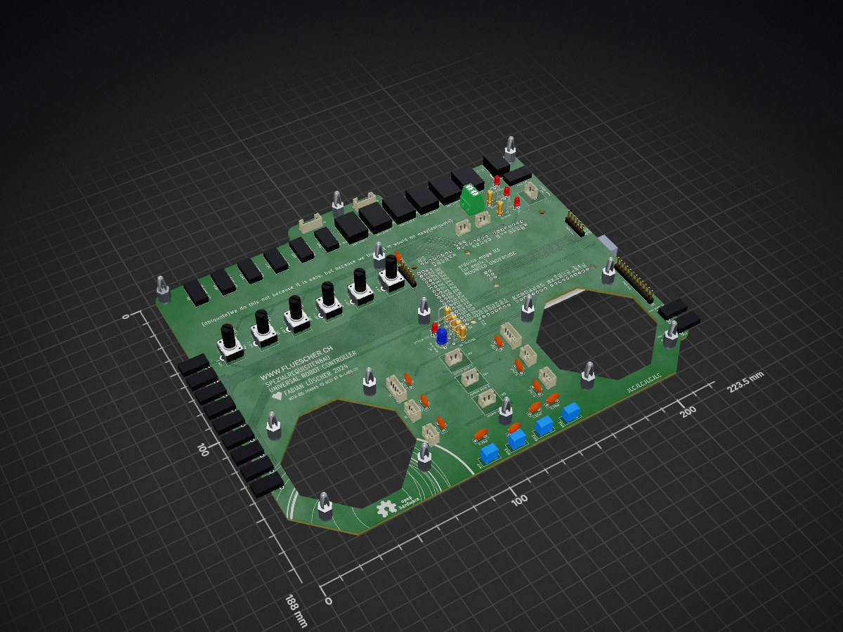
 falue/universalRobotController1
DIY RC transmitter and receiver
UniversalRobotTx is an open-source printed circuit board by falue, from the falue/universalRobotController repository on GitHub. It is a 2-layer board of 223.5 × 188 mm with 97 parts on 109 nets, routed with 432 tracks and 40 vias.
Its parts include 28 switches, 16 capacitors, 15 connectors, 6 resistors and 5 diodes. It belongs with the AVR (ATmega, ATtiny) boards of this library.
This repository includes transmitter (TX) and receiver (RX) arduino files for a remote controlled robot of any form.
The transmitter is a custom build to have full control over input mixing, skewing and do all sorts of dependencies. It depends on a custom PCB, or like a thousand wires. The receiver end can be a robot or whatever.
This relies on OrangeRx products by hobbyking for Tx/Rx and uses the (legacy) DSM2/DSMX† protocols for a reliable, digital communication. with a "range of up to 3km (line of sight)". I'm sure though this works with any RC transmitter that uses iBUs / ppm.
Based on James Brutons RemoteDSM:
† "The DSM in DSMX stands for Digital Spectrum Modulation and is what creates pure digital control providing an impenetrable radio link immune to all types of interference." (Soruce ↗)
Depending if you need 10 or 20 channels you can choose to use a second transmitter.
The second transmitter leads to more fluctation and/or longer duration of the main loop() though. If you need snappy response times, reconsider using a second transmitter.
| Num of Transmitters | Range (ms) | Average (ms) | Median (ms) |
|---|---|---|---|
| 1 | 30-69 | 31 | 32 |
| 2 | 28-70 | 45 | 33 |
As the Windows software "rx_secure_configurator ↗" for the receiver ↗ to set some settings on the receiver is very buggy, buy the OrangeRx Program box ↗.
📝 NOTE: Red LED on remote (on the transmitter) does not turn on if no signal is sent to the PPM pin.
📝 NOTE: Always power on robot receiver first, then remote.
📝 NOTE: If turned off remote while robot receiver is on, restart robot receiver as well to reset connection. Turning off robot receiver while remote is still on, restarting robot receiver again auto connects again.
| Qty | Value | Footprint | References |
|---|---|---|---|
| 16 | 0.33uF | Capacitor_THT:C_Disc_D7.0mm_W2.5mm_P5.00mm | C1, C2, C3, C4, C5, C6, C7, C8, C9, C10, C11, C12, C13, C17, C18, C19 |
| 14 | MountingHole | MountingHole:MountingHole_3mm | H1, H2, H3, H4, H5, H6, H7, H8, H10, H11, H13, H14, H15, H16 |
| 6 | R=220Ω | Resistor_THT:R_Axial_DIN0309_L9.0mm_D3.2mm_P5.08mm_Vertical | R1, R2, R3, R4, R5, R6 |
| 2 | Not used | Connector_PinHeader_2.54mm:PinHeader_1x06_P2.54mm_Vertical | J10, J14 |
| 1 | 12V POWER LED | LED_THT:LED_D3.0mm | D5 |
| 1 | 5V LED | Connector_JST:JST_EH_B2B-EH-A_1x02_P2.50mm_Vertical | J15 |
| 1 | Arduino_Mega2560_R3_Shield | PCM_arduino-library:Arduino_Mega2560_R3_Shield | A1 |
| 1 | BATTERY INPUT 7-12V | TerminalBlock_Phoenix:TerminalBlock_Phoenix_MKDS-1,5-2-5.08_1x02_P5.08mm_Horizontal | J3 |
| 1 | In: 7-12V | Connector_BarrelJack:BarrelJack_Kycon_KLDX-0202-xC_Horizontal | J12 |
| 1 | L-X | Connector_JST:JST_PH_B3B-PH-K_1x03_P2.00mm_Vertical | J8 |
| 1 | L-Y | Connector_JST:JST_PH_B3B-PH-K_1x03_P2.00mm_Vertical | J9 |
| 1 | L-Z | Connector_JST:JST_PH_B5B-PH-K_1x05_P2.00mm_Vertical | J1 |
| 1 | Not used | Connector_PinHeader_2.54mm:PinHeader_1x12_P2.54mm_Vertical | J13 |
| 1 | R-X | Connector_JST:JST_PH_B3B-PH-K_1x03_P2.00mm_Vertical | J7 |
| 1 | R-Y | Connector_JST:JST_PH_B3B-PH-K_1x03_P2.00mm_Vertical | J6 |
| 1 | R-Z | Connector_JST:JST_PH_B5B-PH-K_1x05_P2.00mm_Vertical | J2 |
| 1 | SYS RGB LED | LED_THT:LED_D5.0mm-4_RGB_Wide_Pins | D2 |
| 1 | SYSTEM LED | LED_THT:LED_D3.0mm | D1 |
| 1 | TX 1 LED | LED_THT:LED_D3.0mm | D3 |
| 1 | TX 2 LED | LED_THT:LED_D3.0mm | D4 |
| 1 | Transmitter 1 | Connector_JST:JST_PH_B5B-PH-K_1x05_P2.00mm_Vertical | J4 |
| 1 | Transmitter 2 | Connector_JST:JST_PH_B5B-PH-K_1x05_P2.00mm_Vertical | J5 |
| 1 | VOLTAGE METER | Connector_JST:JST_EH_B2B-EH-A_1x02_P2.50mm_Vertical | J11 |
| 1 | main I/O | Button_Switch_THT:Toggle_switch_3P_5.08 | SW7 |
| 1 | poti 1 | Potentiometer_THT:Potentiometer_Bourns_PTV09A-1_Single_Vertical | RV1 |
| 1 | poti 2 | Potentiometer_THT:Potentiometer_Bourns_PTV09A-1_Single_Vertical | RV2 |
| 1 | poti 3 | Potentiometer_THT:Potentiometer_Bourns_PTV09A-1_Single_Vertical | RV3 |
| 1 | poti 4 | Potentiometer_THT:Potentiometer_Bourns_PTV09A-1_Single_Vertical | RV4 |
| 1 | poti 5 | Potentiometer_THT:Potentiometer_Bourns_PTV09A-1_Single_Vertical | RV5 |
| 1 | poti 6 | Potentiometer_THT:Potentiometer_Bourns_PTV09A-1_Single_Vertical | RV6 |
| 1 | reset arduino | FL:Drucktaster_FL_Mentor_1852.6231 | SW6 |
| 1 | system push 1 | FL:Drucktaster_FL_Mentor_1852.6231 | SW3 |
| 1 | system push 2 | FL:Drucktaster_FL_Mentor_1852.6231 | SW4 |
| 1 | system push 3 | FL:Drucktaster_FL_Mentor_1852.6231 | SW5 |
| 1 | trimL-X | Potentiometer_THT:Potentiometer_Bourns_3386X_Horizontal | RV7 |
| 1 | trimL-Y | Potentiometer_THT:Potentiometer_Bourns_3386X_Horizontal | RV13 |
| 1 | trimR-X | Potentiometer_THT:Potentiometer_Bourns_3386X_Horizontal | RV12 |
| 1 | trimR-Y | Potentiometer_THT:Potentiometer_Bourns_3386X_Horizontal | RV11 |
| 1 | user push 1 | Button_Switch_THT:SW_TH_Tactile_FL_thingy | SW2 |
| 1 | user push 10 | Button_Switch_THT:SW_Push_1P2T_Horizontal_FL_RND_210-00255 | SW21 |
| 1 | user push 11 | Button_Switch_THT:SW_Push_1P2T_Horizontal_FL_RND_210-00255 | SW22 |
| 1 | user push 12 | Button_Switch_THT:SW_Push_1P2T_Horizontal_FL_RND_210-00255 | SW23 |
| 1 | user push 13 | Button_Switch_THT:SW_Push_1P2T_Horizontal_FL_RND_210-00255 | SW24 |
| 1 | user push 14 | Button_Switch_THT:SW_Push_1P2T_Horizontal_FL_RND_210-00255 | SW25 |
| 1 | user push 15 | Button_Switch_THT:SW_Push_1P2T_Horizontal_FL_RND_210-00255 | SW26 |
| 1 | user push 16 | Button_Switch_THT:SW_Push_1P2T_Horizontal_FL_RND_210-00255 | SW27 |
| 1 | user push 17 | Button_Switch_THT:SW_Push_1P2T_Horizontal_FL_RND_210-00255 | SW28 |
| 1 | user push 2 | Button_Switch_THT:SW_TH_Tactile_FL_thingy | SW8 |
| 1 | user push 3 | Button_Switch_THT:SW_TH_Tactile_FL_thingy | SW9 |
| 1 | user push 4 | Button_Switch_THT:SW_TH_Tactile_FL_thingy | SW10 |
| 1 | user push 5 | Button_Switch_THT:SW_TH_Tactile_FL_thingy | SW11 |
| 1 | user push 6 | Button_Switch_THT:SW_TH_Tactile_FL_thingy | SW12 |
| 1 | user push 7 | Button_Switch_THT:SW_Push_1P2T_Horizontal_FL_RND_210-00255 | SW18 |
| 1 | user push 8 | Button_Switch_THT:SW_Push_1P2T_Horizontal_FL_RND_210-00255 | SW19 |
| 1 | user push 9 | Button_Switch_THT:SW_Push_1P2T_Horizontal_FL_RND_210-00255 | SW20 |
| 1 | user switch 01 | Button_Switch_THT:Toggle_switch_3P_5.08 | SW1 |
| 1 | user switch 02 | Button_Switch_THT:Toggle_switch_3P_5.08 | SW14 |
| 1 | user switch 03 | Button_Switch_THT:Toggle_switch_3P_5.08 | SW13 |
| 1 | user switch 04 | Button_Switch_THT:Toggle_switch_3P_5.08 | SW17 |
| 1 | user switch 05 | Button_Switch_THT:Toggle_switch_3P_5.08 | SW15 |
| 1 | user switch 06 | Button_Switch_THT:Toggle_switch_3P_5.08 | SW16 |
The 95 most common of 97 parts.
It measures 223.5 × 188 mm and has 2 copper layers, 1.6 mm thick.
97 parts. The full list of its parts is on this page, with links to each part's symbol and footprint where PCBKit's library has them.
From the falue/universalRobotController repository on GitHub, at the commit this page was made from: the board is kicad/universalRobotTx/universalRobotTx.kicad_pcb and its schematic kicad/universalRobotRx/universalRobotRx.kicad_sch. PCBKit opens the board in the browser, with nothing to install.
Its repository states no licence, so its author keeps all rights: ask falue before reusing the design.


freeDSP/freeDSP-aurora
freeDSP ADAU1452 with 8 analog input, 8 analog outputs, S/P-DIF I/O, ADAT I/O, USB Audio Class2, WiFi, Bluetooth

matthewcieplak/super-sixteen
Code and schematics for the Super Sixteen Eurorack sequencer

ZeroPhone/ZeroPhone-PCBs
PCB files for ZeroPhone - for gerbers and schematics, go to "Releases" tab!


cnlohr/cnhardware
My dumping grounds for all my kicad projects and random hardware bringup.