4 layers70 × 72 mm
 FallenFireGit/RP2040-Devboard
This repository contains my work with the RP2040 microcontroller, where I experimented with embedded programming, basic hardware integration, and peripherals like LEDs and buttons. It documents my learning process, including setup, coding, and troubleshooting, as I built a better understanding of how microcontrollers work in real-world applications
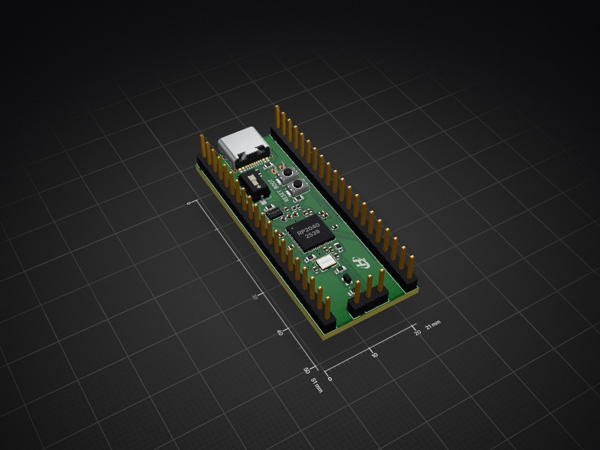
RP2040 CNC Controller is an open-source printed circuit board by FallenFireGit, from the FallenFireGit/RP2040-Devboard repository on GitHub. It is a 4-layer board of 21 × 51 mm with 56 parts on 73 nets, routed with 537 tracks and 49 vias.
It is built around the RP2040, W25Q64JVZPIQ and AP2112K-3.3, with the SS14 among its other parts. Its parts include 21 capacitors, 16 resistors, 6 connectors, 4 ICs and 4 diodes. It belongs with the robots and motor control boards and the RP2040 boards of this library.


This project is a fully custom PCB based on the RP2040 microcontroller, designed as an upgraded alternative to standard dev boards like the Raspberry Pi Pico.
The goal was to create a board that is:
8MB Flash (upgraded from 2MB)
MicroSD Card Slot
Boot Button – Easy entry into bootloader mode
Reset Button – Quick system reset during development
Status LED (Bi-color)
Master Power Switch
LiPo Battery Support
~600mA Current Capacity
3.3V Enable Control (3V3_EN)
Optimized Power Traces
Wider 3.3V and GND lines for:
Switched to a higher current voltage regulator for better performance
Removed unnecessary components after redesign
Standardized passive components to 0603:
4-Layer PCB
Double-sided component placement
Capacitors
Resistors
Total Price of Passive Components ~ $1.90 (Depends on who you buy it from)
Diodes & Clock ~ $1.16
Connectors / I/O ~ $4.75
Switches ~ $1.20
ICs / Chips
| Component | Quantity | Price (Est.) |
|---|---|---|
| Passives (Capacitors & Resistors) | 38 | $1.90 |
| Diodes (SS14, SB0603W) | 4 | $0.90 |
| Clock (12MHz Crystal) | 1 | $0.70 |
| Connectors / I/O (USB-C, Headers, JST, MicroSD) | 6 | $4.75 |
| Switches (Push buttons, Slider) | 3 | $1.20 |
| RP2040 (Microcontroller) | 1 | $0.92 |
| MCP73831-2-OT (Battery Charger) | 1 | $0.76 |
| W25Q64JVZPIQ (Flash Memory) | 1 | $1.44 |
| AP2112K-3.3 (Voltage Regulator) | 1 | $0.57 |
| TOTAL | 56 | $13.14 |
| Qty | Value | Footprint | References |
|---|---|---|---|
| 10 | 0.1uF | Capacitor_SMD:C_0402_1005Metric | C2, C3, C4, C5, C6, C7, C9, C11, C12, C17 |
| 5 | 10uF | Capacitor_SMD:C_0805_2012Metric | C13, C14, C19, C20, C21 |
| 3 | 1K | Resistor_SMD:R_0603_1608Metric | R6, R9, R14 |
| 3 | 47K | Resistor_SMD:R_0603_1608Metric | R8, R12, R13 |
| 3 | SS14 | Diode_SMD:D_SOD-123 | D1, D3, D4 |
| 2 | 100K | Resistor_SMD:R_0603_1608Metric | R5, R11 |
| 2 | 10K | Resistor_SMD:R_0603_1608Metric | R7, R17 |
| 2 | 1uF | Capacitor_SMD:C_0402_1005Metric | C1, C10 |
| 2 | 22pF | Capacitor_SMD:C_0402_1005Metric | C15, C16 |
| 2 | 27.4 | Resistor_SMD:R_0402_1005Metric | R3, R4 |
| 2 | 5.1K | Resistor_SMD:R_0603_1608Metric | R1, R2 |
| 2 | Conn_01x20 | Connector_PinHeader_2.54mm:PinHeader_1x20_P2.54mm_Vertical | J2, J3 |
| 2 | SW_Push | Button_Switch_SMD:SW_Push_SPST_NO_Alps_SKRK | BOOT, RESET |
| 1 | 0.5uF | Capacitor_SMD:C_0402_1005Metric | C18 |
| 1 | 100nF | Capacitor_SMD:C_0402_1005Metric | C22 |
| 1 | 12MHz | Crystal:Crystal_SMD_3225-4Pin_3.2x2.5mm | Y1 |
| 1 | 200K | Resistor_SMD:R_0603_1608Metric | R10 |
| 1 | 2K | Resistor_SMD:R_0603_1608Metric | R15 |
| 1 | AP2112K-3.3 | Package_TO_SOT_SMD:SOT-23-5 | U5 |
| 1 | Conn_01x02_Pin | Connector_JST:JST_PH_S2B-PH-K_1x02_P2.00mm_Horizontal | J6 |
| 1 | Conn_01x03 | Connector_PinHeader_2.54mm:PinHeader_1x03_P2.54mm_Vertical | J4 |
| 1 | LOGO | LOGO | G*** |
| 1 | MCP73831-2-OT | Package_TO_SOT_SMD:SOT-23-5 | U2 |
| 1 | Micro_SD_Card | Micro_SD:Micro_SD | J5 |
| 1 | RP2040 | Package_DFN_QFN:QFN-56-1EP_7x7mm_P0.4mm_EP3.2x3.2mm | U1 |
| 1 | SW_Slider | Button_Switch_SMD:SW_DIP_SPSTx01_Slide_6.7x4.1mm_W6.73mm_P2.54mm_LowProfile_JPin | ON |
| 1 | USB_C_Receptacle_USB2.0_14P | Connector_USB:USB_C_Receptacle_HRO_TYPE-C-31-M-12 | J1 |
| 1 | W25Q64JVZPIQ | Package_SON:Winbond_USON-8-1EP_3x2mm_P0.5mm_EP0.2x1.6mm | U3 |
| 1 | ~ | Library:SB0603WC01RG | D2 |
It measures 21 × 51 mm and has 4 copper layers, 1.6 mm thick.
56 parts, built around the RP2040, W25Q64JVZPIQ, AP2112K-3.3 and SS14. The full list of its parts is on this page, with links to each part's symbol and footprint where PCBKit's library has them.
From the FallenFireGit/RP2040-Devboard repository on GitHub, at the commit this page was made from: the board is PCB Files/RP2040_CNC_Controller.kicad_pcb and its schematic PCB Files/RP2040_CNC_Controller.kicad_sch. PCBKit opens the board in the browser, with nothing to install.
Its repository states no licence, so its author keeps all rights: ask FallenFireGit before reusing the design.


hackclub/hackducky
The hackclub themed USB rubber ducky ! - Check out hackducky

VTC-WISDOM/node_hardware
Schematic/PCB designs for WiSDOM nodes, also includes a few other related hardware projects

Cherry-Blossom-Development/GreywireStudio
GreywireStudio - a combined software/hardware product