4 layers80 × 50 mm
HadesNT
pms67/HadesFCS
Complete flight control system designed from scratch. Hardware designed with KiCad.
103 parts1kBSD-3-Clause
 fablackner/keysatron
Keysatron is built around the STM32F405RGT6 ARM Cortex-M4 microcontroller, which features two independent USB OTG controllers: 1.
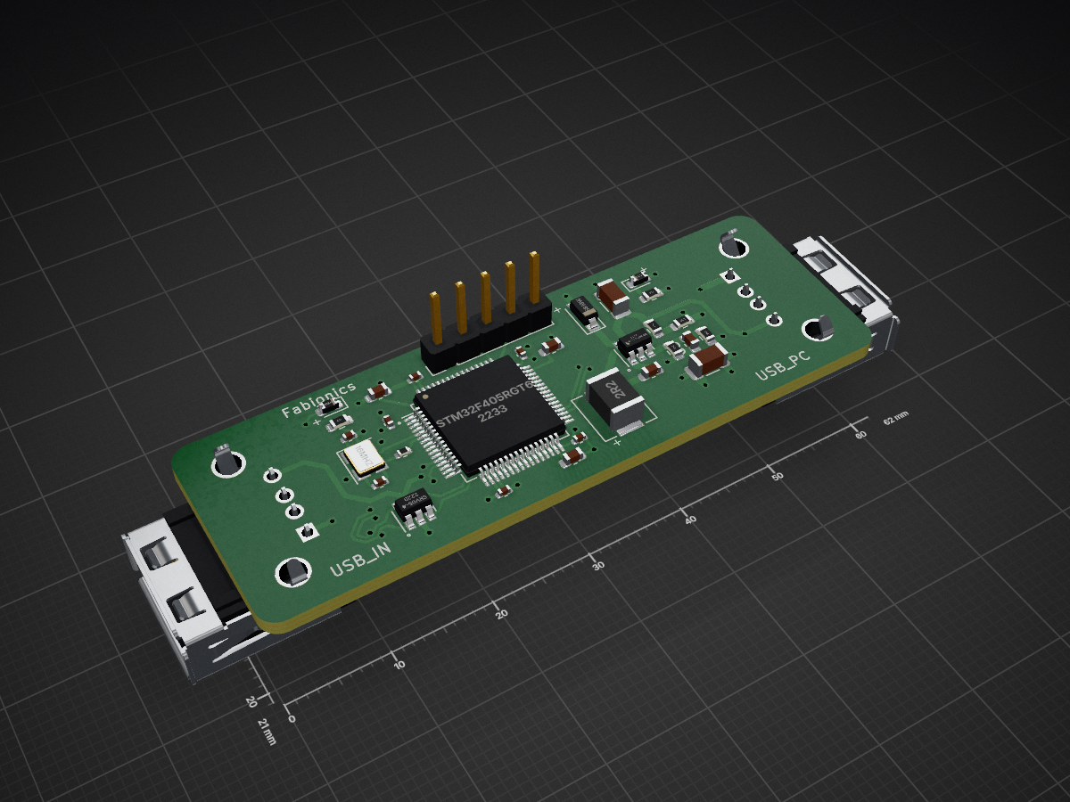
Keysatron is an open-source printed circuit board by fablackner, from the fablackner/keysatron repository on GitHub. It is a 4-layer board of 62 × 21 mm with 32 parts on 22 nets, routed with 282 tracks and 48 vias.
It is built around the STM32F405RGT6, MP2451DT-LF-Z and SRV05-4, with the B5819W among its other parts. Its parts include 14 capacitors, 7 resistors, 3 ICs, 3 diodes and 3 connectors. It belongs with the STM32 boards of this library.


Keysatron is an inline USB-to-USB hardware adapter designed to intercept, transform, and remap USB HID keyboard input in real-time. By sitting transparently between your physical keyboard and your computer, it allows hardware-level key translation—such as converting German ISO (QWERTZ) keystrokes into Colemak ISO layout—without requiring any software, drivers, or administrative privileges on the host operating system.
Keysatron is built around the STM32F405RGT6 ARM Cortex-M4 microcontroller, which features two independent USB OTG controllers:
USB_IN (J2) to read input reports from connected USB keyboards.USB_PC (J3) to emulate a USB HID keyboard to the host PC.| Feature | Description |
|---|---|
| Microcontroller | STM32F405RGT6 (ARM Cortex-M4 @ 168 MHz, 1 MB Flash, 192 KB SRAM) |
Input Port (USB_IN, J2) | USB Type-A Female – USB OTG FS Host (PA11 DM, PA12 DP) |
Output Port (USB_PC, J3) | USB Type-A Female / Cable – USB OTG HS Device in FS mode (PB14 DM, PB15 DP) |
| Power Supply | MP2451DT step-down buck converter (5 V VBUS to 3.3 V core rail) |
| Oscillator | 16 MHz external crystal (HSE) |
| ESD Protection | SRV05-4 transient voltage suppressors on USB data lines |
| Status LEDs | Red LED (D1): Power indicator (3.3 V rail)Green LED ( D3): Status / activity indicator (GPIO PA0) |
| Debug Header | 5-pin 2.54 mm SWD header (J1) |
J1)The board provides a 5-pin single-row header (J1, 2.54 mm pitch) for programming and debugging via SWD:
[ 1: GND ] [ 2: NRST ] [ 3: CLK ] [ 4: IO ] [ 5: 3.3V ]| Pin | Label | STM32 Pin | Function |
|---|---|---|---|
| 1 | GND | VSS (Pins 12, 18, 60, 63) | Ground |
| 2 | NRST | NRST (Pin 7) | Active-low system reset |
| 3 | CLK | PA14 (Pin 49) | SWD Clock (SWCLK) |
| 4 | IO | PA13 (Pin 46) | SWD Data (SWDIO) |
| 5 | 3.3V | VDD (Pins 1, 13, 19, 32, 48, 64) | 3.3 V Power rail |
When using the built-in ST-LINK/V2-1 on an STM32 Nucleo-64 board (CN4 header):
[!IMPORTANT] Remove the two jumpers on
CN2on the Nucleo board to disconnect the debugger from the onboard microcontroller and direct SWD lines to headerCN4.Note that
CN4Pin 1 (VDD_TARGET) is a voltage-sensing line and does not power the target. Power Keysatron via USB or connect3V3from the Nucleo power header (CN6Pin 4) to KeysatronJ1Pin 5.
Wiring between Nucleo CN4 and Keysatron J1:
| Nucleo CN4 Pin | Nucleo Function | Wire to Keysatron J1 Pin | Keysatron Function |
|---|---|---|---|
| Pin 1 | VDD_TARGET | Pin 5 | 3.3V |
| Pin 2 | SWCLK | Pin 3 | CLK |
| Pin 3 | GND | Pin 1 | GND |
| Pin 4 | SWDIO | Pin 4 | IO |
| Pin 5 | NRST | Pin 2 | NRST |
keysatron.kicad_pcb – KiCad PCB layout (4-layer board)keysatron.sch – KiCad schematickeysatron.pro – KiCad project configurationkeysatron.csv – Bill of Materials (BOM) with LCSC component part numbersassembly/ – Pick-and-place component position files (keysatron-all-pos.csv) and BOM (keysatron_bom.csv) for automated assemblygerber/ – Gerber fabrication files and drill files ready for PCB manufacturing (keysatron_gerber.zip)The companion firmware for this board is maintained in the keysatron-firmware repository.
| Qty | Value | Footprint | References |
|---|---|---|---|
| 5 | 100n | Capacitor_SMD:C_0402_1005Metric | C6, C7, C8, C9, C10 |
| 2 | 12p | Capacitor_SMD:C_0402_1005Metric | C13, C14 |
| 2 | 1k | Resistor_SMD:R_0603_1608Metric | R5, R6 |
| 2 | 2u2 | Capacitor_SMD:C_0603_1608Metric | C11, C12 |
| 2 | USB | Connector_USB:USB_A_Molex_67643_Horizontal | J2, J3 |
| 1 | 100k | Resistor_SMD:R_0603_1608Metric | R1 |
| 1 | 100n | Capacitor_SMD:C_0603_1608Metric | C1 |
| 1 | 10u | Capacitor_SMD:C_1206_3216Metric | C4 |
| 1 | 120k | Resistor_SMD:R_0603_1608Metric | R2 |
| 1 | 16Mhz | Crystal:Crystal_SMD_3225-4Pin_3.2x2.5mm | Y1 |
| 1 | 2.2u | Inductor_SMD:L_Sunlord_MWSA0518_5.4x5.2mm | L1 |
| 1 | 33p | Capacitor_SMD:C_0603_1608Metric | C3 |
| 1 | 39k | Resistor_SMD:R_0603_1608Metric | R4 |
| 1 | 47 | Resistor_SMD:R_0402_1005Metric | R7 |
| 1 | 4u7 | Capacitor_SMD:C_1206_3216Metric | C2 |
| 1 | 4u7 | Capacitor_SMD:C_0603_1608Metric | C5 |
| 1 | 68k | Resistor_SMD:R_0603_1608Metric | R3 |
| 1 | B5819W | Diode_SMD:D_SOD-123 | D2 |
| 1 | GREEN | Diode_SMD:D_0603_1608Metric | D3 |
| 1 | MP2451DT-LF-Z | Package_TO_SOT_SMD:SOT-23-6 | U1 |
| 1 | RED | Diode_SMD:D_0603_1608Metric | D1 |
| 1 | SRV05-4 | Package_TO_SOT_SMD:SOT-23-6 | U2 |
| 1 | STM32F405RGT6 | Package_QFP:LQFP-64_10x10mm_P0.5mm | U3 |
| 1 | SWD | Connector_PinHeader_2.54mm:PinHeader_1x05_P2.54mm_Vertical | J1 |
It measures 62 × 21 mm and has 4 copper layers, 1.6 mm thick.
32 parts, built around the STM32F405RGT6, MP2451DT-LF-Z, SRV05-4 and B5819W. The full list of its parts is on this page, with links to each part's symbol and footprint where PCBKit's library has them.
From the fablackner/keysatron repository on GitHub, at the commit this page was made from: the board is keysatron.kicad_pcb. PCBKit opens the board in the browser, with nothing to install.
Its repository states no licence, so its author keeps all rights: ask fablackner before reusing the design.
pms67/HadesFCS
Complete flight control system designed from scratch. Hardware designed with KiCad.

tadzio8425/Micromouse
Micromouse developed by the IEEE Robotics and Automation Society chapter of the Universidad de Los Andes, Bogotá (2023-2024).

R8bert/esp32-psu
A smart, programmable lab power supply controlled by an ESP32 microcontroller. This project combines hardware design and firmware development to provide precise, remote control over voltage and current using a…


pms67/LittleBrain-STM32F4-Sensorboard
STM32F4-based PCB interfacing with a variety of sensors.

