
2 layers38.7 × 28.6 mm
 f1ac0/GBS-Control2
Boards for GBS-8200 and GBS-Control firmware
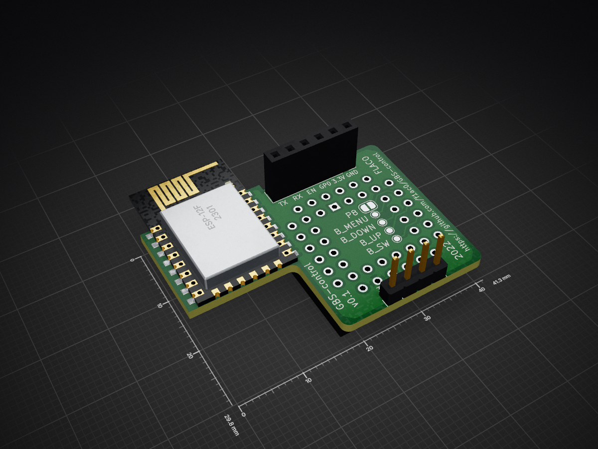
GBS Control is an open-source printed circuit board by f1ac0, from the f1ac0/GBS-Control repository on GitHub. It is a 2-layer board of 41.3 × 29.8 mm with 17 parts on 55 nets, routed with 110 tracks and 11 vias.
It is built around the ESP-12F. Its parts include 4 resistors, 3 capacitors, 2 ICs and 2 connectors. It belongs with the ESP8266 boards of this library.
GBS-control, https://github.com/ramapcsx2/gbs-control, is an alternative firmware for Tvia Trueview5725 based upscalers / video converter boards such as the "GBS8200".
This repository contains the boards I designed to improve my own GBS-8200 with GBS-control using ESP12/ESP-M2 modules.
This is a hobbyist project, it comes with no warranty and no support.
This board is not endorsed by firmware author, please don't bother him with issues you might have because of it.
I publish my work under the CC-BY-NC-SA license.
If you find it useful and want to reward my hard work : I am always looking for Amiga/Amstrad CPC hardware to repair and hack, please contact me.
The socket must be prepared before soldering : remove the 4 small stands inside the socket and file plastic from its top up to the contacts so the socket can plug on top of the PLCC chip without popping out. Be careful to remove plastic debris, and check its orientation before soldering under the PCB.
Check for shorts at least between power traces before applying power !
The programming port does not need to be soldered since it needs to be programmed just once : you can just hold it in place during the few seconds required for programming with an USB to serial adapter. When you want to program it, remember to short GPIO0 to ground before applying power.
Plug the GBS-control board on the PLCC controller. Connect the clock generator board on the clock port.
There is no need to populate P8 since it is shorted by the board. It also takes the 3.3V from the PLCC chip so no additional power connection is required.
See GBS-control wiki for software setup.
| Qty | Value | Footprint | References |
|---|---|---|---|
| 4 | 10K | Resistor_SMD:R_0805_2012Metric | R1, R2, R3, R4 |
| 2 | 100n | Capacitor_SMD:C_0805_2012Metric | C2, C3 |
| 1 | 10u | Capacitor_SMD:C_0805_2012Metric | C1 |
| 1 | B_DOWN | TestPoint:TestPoint_Pad_D1.0mm | TP2 |
| 1 | B_MENU | TestPoint:TestPoint_Pad_D1.0mm | TP4 |
| 1 | B_SW | TestPoint:TestPoint_Pad_D1.0mm | TP3 |
| 1 | B_UP | TestPoint:TestPoint_Pad_D1.0mm | TP1 |
| 1 | Clock port | Connector_PinHeader_2.54mm:PinHeader_1x04_P2.54mm_Vertical | J2 |
| 1 | ESP-12F | Sassa:ESP-12E_No-bottom-pins | U2 |
| 1 | Jumper_2_Bridged | Jumper:SolderJumper-2_P1.3mm_Bridged_RoundedPad1.0x1.5mm | JP1 |
| 1 | License | Sassa:CC_BY_NC_SA_long_silkscreen | FID1 |
| 1 | PLCC-44 socket | Sassa:PLCC-44_THT-SocketOnTop | U1 |
| 1 | PROG | Connector_PinSocket_2.54mm:PinSocket_1x06_P2.54mm_Vertical | J1 |


Staacks/there.oughta.be
Projects featured on my blog at https://there.oughta.be

klein0r/pcb-ws2812-wifi-controller
WiFi Controller for WS2812 LED Stripes

reneklootwijk/mideahvac-dongle
This repository contains the hardware design of a WiFi dongle for Midea-like airconditioners and humidifiers. Midea provides a WiFi dongle (SK102/SK103), either as optional feature or built-in, to control the appliances…

gadjet/Window-Door-sensor-Version-5
Version 5 of the Window/Door sensor project this time with ultra low current consumption

horvathgergo/esp8266-for-uppatvind
Smart controller for IKEA Uppåtvind Air Purifiers
It measures 41.3 × 29.8 mm and has 2 copper layers, 1.6 mm thick.
17 parts, built around the ESP-12F. The full list of its parts is on this page, with links to each part's symbol and footprint where PCBKit's library has them.
From the f1ac0/GBS-Control repository on GitHub, at the commit this page was made from: the board is GBS-Control-12F/GBS-Control.kicad_pcb and its schematic GBS-Control-12F/GBS-Control.kicad_sch. PCBKit opens the board in the browser, with nothing to install.
Its repository states no licence, so its author keeps all rights: ask f1ac0 before reusing the design.