

2 layers32.9 × 53.3 mm

 Kaldek/rat-ratgdo511
Open source schematics for ratgdo PCB
RatGDO OpenSource Bare ESP8266 is an open-source printed circuit board by Kaldek, from the Kaldek/rat-ratgdo repository on GitHub, published under the MIT licence. It is a 2-layer board of 55 × 82.7 mm with 24 parts on 26 nets, routed with 126 tracks and 8 vias.
It is built around the ESP-12F and AO3400A. Its parts include 8 resistors, 6 connectors, 2 ICs, 2 transistors and 1 capacitor. It belongs with the ESP8266 boards of this library.
A reworking of the Bare ESP8266 board design that uses USB-C for power instead of an LM2596 submodule, and uses just one GDO connector header to allow for a smaller board footprint.
Compatable with RatGDO ESPHome software for the v2.5 official board.
Populating the Flash switch, Reset switch, and ICSP header are optional, but will make first time programming easier.
This board uses a 6-pin power-only USB-C jack that can be either hand soldered or paste reflowed. It's a normal 5V USB sink device, so any "dumb" USB wall-wart can be used.
It can also be powered via the 3.3V pin of the ICSP header - there's no need to connect USB while serial programming it.
If you wish to power the device directly from the programming header using 3.3V, you can skip populating the USB-C port, resistors R2 and R3, and the LDO regulator CR1, but you should ensure you're using a stable and regulated 3.3V supply.
If your GDO has battery backup system, I'd recommend using one of the LM2996 module based boards in this repository instead of this one.
The USB-C port on this board is for power only - you need to use the ICSP programming header with a seperate TTL-level RS232 programming interface to load the initial firmware.
The ICSP header will mate directly with the SparkFun Serial Basic Breakout for programming, but any 3.3V RS232 interface can be used by connecting TX, RX, VCC and GND appropriately.
Auto reset via serial hardware control lines isn't supported - you'll need to press the Reset button manually after programming, or power cycle the device.
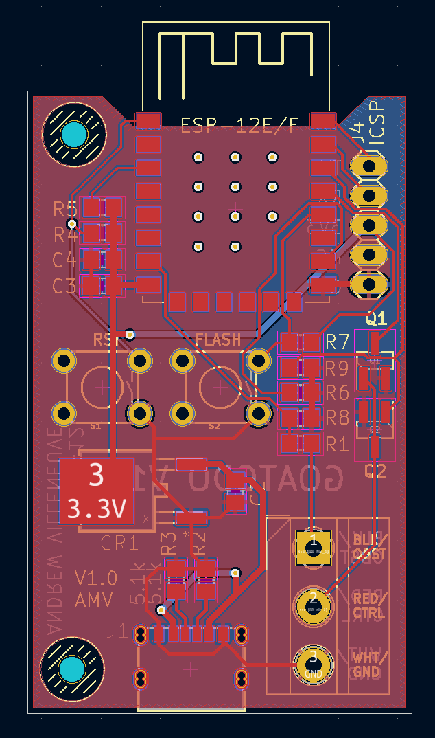
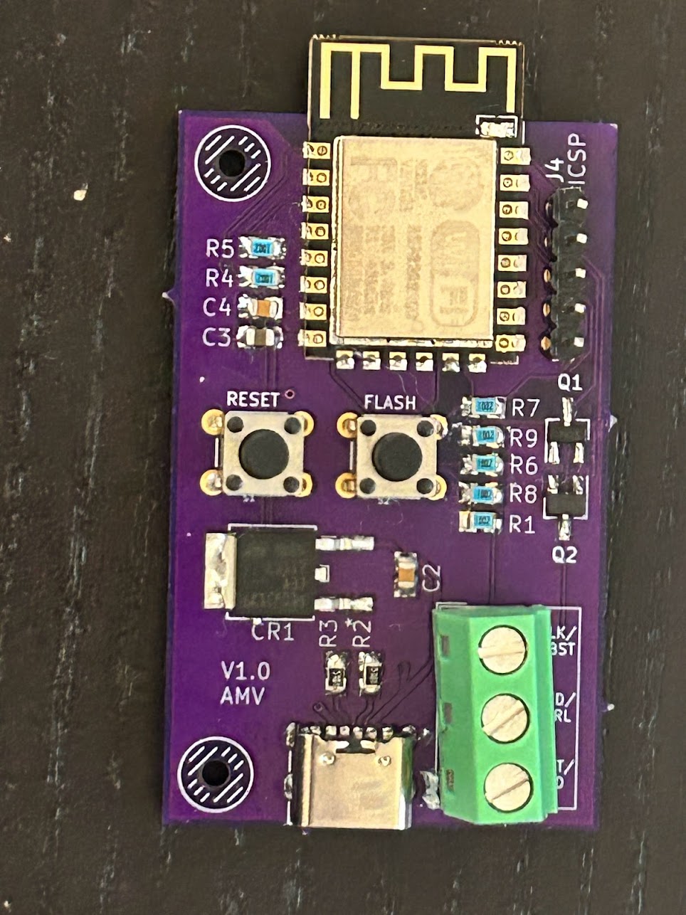
| Qty | Value | Footprint | References |
|---|---|---|---|
| 8 | 10k | Resistor_SMD:R_0805_2012Metric | R1, R2, R3, R4, R5, R6, R7, R8 |
| 4 | MountingHole_5mm | MountingHole:MountingHole_5mm | H1, H1, H1, H1 |
| 1 | 0.1uf | Capacitor_SMD:C_0805_2012Metric | C1 |
| 1 | 2N7002 | Package_TO_SOT_SMD:SOT-23 | Q1 |
| 1 | AO3400A | Package_TO_SOT_SMD:SOT-23 | Q2 |
| 1 | Conn_01x02 | Connector_PinHeader_2.54mm:PinHeader_1x02_P2.54mm_Vertical | J6 |
| 1 | Conn_01x04 | Connector_PinSocket_2.54mm:PinSocket_1x04_P2.54mm_Vertical | J4 |
| 1 | ESP-12F | RF_Module:ESP-12E | U1 |
| 1 | LM2596 DC-DC Converter | DC_DC_LM2596_small:DC_DC_LM2596_small | U2 |
| 1 | SW_Push | Button_Switch_SMD:SW_SPST_EVQQ2 | SW1 |
| 1 | Screw_Terminal_01x02 | TerminalBlock_Phoenix:TerminalBlock_Phoenix_MKDS-1,5-2_1x02_P5.00mm_Horizontal | J5 |
| 1 | Screw_Terminal_01x03 | Connector_Phoenix_MC:PhoenixContact_MCV_1,5_3-G-3.5_1x03_P3.50mm_Vertical | J2 |
| 1 | Screw_Terminal_01x03 | Connector_PinSocket_2.54mm:PinSocket_1x03_P2.54mm_Vertical | J3 |
| 1 | Screw_Terminal_01x03 | TerminalBlock_Phoenix:TerminalBlock_Phoenix_MKDS-1,5-3_1x03_P5.00mm_Horizontal | J1 |

Kaldek/rat-ratgdo
Open source schematics for ratgdo PCB


abzman/esp-IoT-boards
R5v: 1.9K for the red LED, 3.9K for the blue LED

unicab369/ESP-MESS
I am building a Wireless Bridge System that can manage multiple devices using a variety of wireless technologies.


Staacks/there.oughta.be
Projects featured on my blog at https://there.oughta.be

klein0r/pcb-ws2812-wifi-controller
WiFi Controller for WS2812 LED Stripes

reneklootwijk/mideahvac-dongle
This repository contains the hardware design of a WiFi dongle for Midea-like airconditioners and humidifiers. Midea provides a WiFi dongle (SK102/SK103), either as optional feature or built-in, to control the appliances…
It measures 55 × 82.7 mm and has 2 copper layers, 1.6 mm thick.
24 parts, built around the ESP-12F and AO3400A. The full list of its parts is on this page, with links to each part's symbol and footprint where PCBKit's library has them.
From the Kaldek/rat-ratgdo repository on GitHub, at the commit this page was made from: the board is kicad_files/Bare ESP8266/RatGDO-OpenSource-Bare-ESP8266.kicad_pcb and its schematic kicad_files/Bare ESP8266 USB/goatgdo.kicad_sch. PCBKit opens the board in the browser, with nothing to install.
Its repository publishes it under the MIT licence: you may reuse it on that licence's terms (keep the author's notice, and for a copyleft licence share your changes alike).