
2 layers18 × 49.1 mm
SommerESP ETHmodule
exico91/SommerESP
A plug and play ESP32-C3 board to control Sommer garage doors
5 parts29MIT

 exico91/SommerESP29
A plug and play ESP32-C3 board to control Sommer garage doors
SommerESP is an open-source printed circuit board by exico91, from the exico91/SommerESP repository on GitHub, published under the MIT licence. It is a 2-layer board of 76.8 × 23.5 mm with 41 parts on 31 nets, routed with 238 tracks and 34 vias.
It is built around the ESP32-C3-WROOM-02-H4, 2N7002DW and FAUL0630-330MT, with the SS36, SS54 and STN3NF06 among its other parts. Its parts include 9 resistors, 6 connectors, 5 diodes, 4 capacitors and 2 ICs. It belongs with the ESP32 and RISC-V boards of this library.


A plug and play ESP32-C3 board to control Sommer garage doors based on ESPHOME
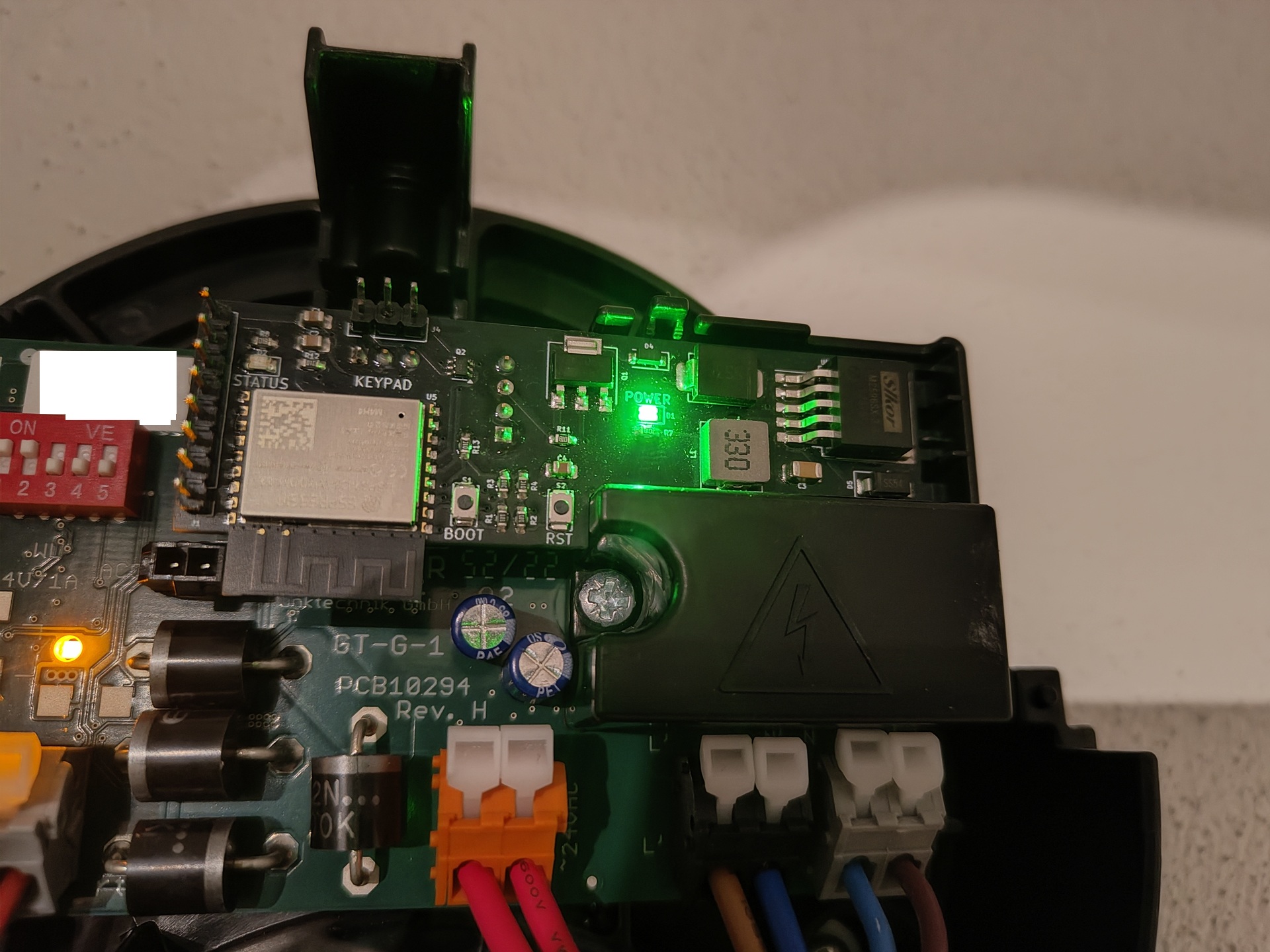
This combo is designed to replace the Sommer Conex Module and the Sommer Output OC Module.
[!TIP] Where to get in touch
- 🐛 Issues: report a problem or suggest an improvement for the board.
- 💬 Discussions: ask a question or share a compatibility report.
The Sommer Conex Module is designed to replicate the press of the buttons on the controller of the garage door and the Sommer Output OC just provide the signal for the status and 24 Volts DC.
This project takes the 24V and converts it to 3.3V for the ESP32-C3 module, the DC regulator on the power board can take from 4.5V to 40V and cleanly output 3.3V then transfer it to the Control board along with the status signal.
The ESP controller simulate the press of the buttons using a pair of optocouplers, simple enough. You can also attach other things to this board, I left a couple of GPIOs on exposed pins along with the serial connection required to flash the module.
You can buy here the kit that includes the two boards and a cable or you can build one yourself. You can find the BOM (bill of materials) here and the gerber files here. There are a lot of PCB Manufacturers. The most known are PCBWay and JLCPCB. I used both and are good.
[!NOTE] The ethernet module (W5500) yaml is available here and the KiCad project here.
If your installation requires better WiFi reception, an external antenna version is available. You will need:
Connect the adapter cable to the U.FL connector on the board and attach the external antenna.
To flash connect you serial programmer to the exposed pins on the controller board. DO NOT connect the programmer while the board is connected to the power board or inserted in the Sommer controller. From top to bottom the pins are in this order:
3.3V GPIO05 RX TX GPIO18 GPIO19 GPIO03 GND
Press BOOT while powering on the programmer to send the controller in flashing mode.
With the provided yaml, holding the BOOT button for 10 seconds and then releasing it factory resets the board (erases the saved Wi-Fi credentials and preferences, then reboots). It can also be triggered from Home Assistant with the "Factory Reset" button.
This project should work with Sommer Base+, Pro+ and Evo+. The main focus of this project is ESPHome and Homeassistant but you can flash whatever you want on the ESP32-C3. Check here for the pinout.
Confirmed working models:
| Model | Notes | Credits |
|---|---|---|
| 9080 Base+ | The keypad plug is present but there is no keypad, just plug the SommerESP there. | tim-kiefer |
| 2060 Evo+ | The keypad plug has 5 pins instead of 3. Just plug the module on the middle leaving pin 1 and 5 free. See photo for reference here | Severnt |
| 9110 Pro+ | Original installation that created this project. This model has a wall mount control board with a 2 button keypad. | Alessio D |
| S 9050 pro | Need to manually add the DIP switch selector. Check here | M3c4tr0x |
| A800 XL | Compatible but the Conex pins are shifted. Requires board version 2 or jumper cables. | jkremlacek |
Tested SommerESP on another model? Please share your result in Discussions, whether it worked or not.
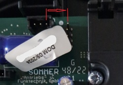
[!WARNING] Please do check the distance between the power pins and the right pin on the button connector. This version of SommerESP is compatible with Sommer boards where the distance is around 9.5 mm or 7.5 mm, just check which is correct and solder the connector for the Conex section in the 9.5 (default) or 7.5 place. If you are buying from Tindie the default will be 9.5, if you need 7.5 please contact me.
| Version | ESPHome | Changes |
|---|---|---|
| 1.0 | — | Initial release |
| 1.3 | 2024.6.1 | Added compatibility for ESPHome 2024.6.1 |
| 2.0 | 2025.8.3 | Added compatibility for ESPHome 2025.8.3 |
| 3.0 | 2026.5.3 | Added compatibility for ESPHome 2026.5.3+, added Ethernet module version |
| 3.1 | 2026.5.3 | Cover stop function is now working |
| 3.2 | 2026.9.0 | Added factory reset function to the BOOT button (hold for 10 seconds) |
| Version | Changes |
|---|---|
| 1.0 - 2.0 | Dual board module with cable |
| 3.0 | Single board, adds Ethernet compatibility. Supports only 9.5 mm distance |
| 3.1 | Adds 7.5 mm distance compatibility |
| 3.2 | Added fabrication holes to the PCB |
| 3.2.1 | Fixed wrong position of J7 |
A thank you to https://github.com/jampez77/garage_door_sensor/ and https://github.com/azrael783/esphome_garagedoor_opener for giving me the ispiration to do this project, a lot of the code and core functionality is similar to these projects. Unfortunately neither did what I needed, cheap and invisible installation. Unfortunately the two Sommer modules (Conex and Output OC) are not cheap for what they are and using a DC-DC converter and relais externally is bulky and unsightly. I took the matter into my hands and now is almost plug and play and places where the two Sommer modules were.
A thank you to M3c4tr0x for a part of the design of the new single board.
| Qty | Value | Footprint | References |
|---|---|---|---|
| 4 | 0603 10k | Resistor_SMD:R_0603_1608Metric_Pad0.98x0.95mm_HandSolder | R3, R4, R12, R13 |
| 3 | 0603 1k | Resistor_SMD:R_0603_1608Metric_Pad0.98x0.95mm_HandSolder | R7, R8, R11 |
| 3 | MountingHole | MountingHole:ToolingHole_1.152mm | H1, H2, H3 |
| 2 | 0603 100ohm | Resistor_SMD:R_0603_1608Metric_Pad0.98x0.95mm_HandSolder | R1, R2 |
| 2 | DEALON TD-1183SN | CustomLibrary:DEALON TD-1183SN-1.5H-160 | S1, S2 |
| 2 | LED | LED_SMD:LED_0805_2012Metric_Pad1.15x1.40mm_HandSolder | D1, D2 |
| 2 | LOGO | LOGO | G***, G*** |
| 1 | +24V | TestPoint:TestPoint_Pad_D2.0mm | TP5 |
| 1 | 0805 100nf | Capacitor_SMD:C_0805_2012Metric_Pad1.18x1.45mm_HandSolder | C2 |
| 1 | 0805 10uf | Capacitor_SMD:C_0805_2012Metric_Pad1.18x1.45mm_HandSolder | C1 |
| 1 | 0805 22uf | Capacitor_SMD:C_0805_2012Metric_Pad1.18x1.45mm_HandSolder | C4 |
| 1 | 1206 220uf | Capacitor_SMD:C_1206_3216Metric_Pad1.33x1.80mm_HandSolder | C3 |
| 1 | 1N4148 | Diode_SMD:D_SOD-123 | D4 |
| 1 | 2N7002DW | Package_TO_SOT_SMD:SOT-363_SC-70-6 | Q2 |
| 1 | BOOT | TestPoint:TestPoint_Pad_2.0x2.0mm | TP1 |
| 1 | ESP32-C3-WROOM-02 | Espressif:ESP32-C3-WROOM-02 | U5 |
| 1 | FAUL0630-330MT | Inductor_SMD:L_Abracon_ASPI-0630LR | L1 |
| 1 | GND | TestPoint:TestPoint_Pad_D2.0mm | TP3 |
| 1 | LM2596SX-3.3/NOPB | Package_TO_SOT_SMD:TO-263-5_TabPin3 | U4 |
| 1 | RST | TestPoint:TestPoint_Pad_2.0x2.0mm | TP2 |
| 1 | SOMMER CONEX BOARD | Connector_PinSocket_2.54mm:PinSocket_1x03_P2.54mm_Vertical | J3 |
| 1 | SOMMER CONEX KEYPAD | Connector_PinHeader_2.54mm:PinHeader_1x03_P2.54mm_Vertical | J4 |
| 1 | SOMMER OUTPUT OC 7.5mm | SommerCustom:PinSocket_1x04_P2.54mm_Vertical_SLIT | J7 |
| 1 | SOMMER OUTPUT OC 8.5mm | SommerCustom:PinSocket_1x04_P2.54mm_Vertical_SLIT | J8 |
| 1 | SOMMER OUTPUT OC 9.5 | SommerCustom:PinSocket_1x04_P2.54mm_Vertical_SLIT | J6 |
| 1 | SOMMERSIG | TestPoint:TestPoint_Pad_D2.0mm | TP4 |
| 1 | SS36 | CustomLibrary:SS32C | D3 |
| 1 | SS54 | Diode_SMD:D_SMA | D5 |
| 1 | STN3NF06 | CustomLibrary:STN3NF06L | Q1 |
| 1 | Serial programmer | Connector_PinHeader_2.54mm:PinHeader_1x08_P2.54mm_Vertical | J1 |
exico91/SommerESP
A plug and play ESP32-C3 board to control Sommer garage doors


dasisdormax/esp32-c3-headset
WIP: An ESP32-C3 based bluetooth headset PCB with headphone jack

Gangwa-Labs/Reflow.Card
PCB Trace Reflow hotplate for the hackaday 2024 Business Card Challenge

siru409/Dilf-seeker
A near field multi beam ultra wideband fmcw radar detector using a novel near field focussed rotman lens

Wassasin/leddimmer
Quick low-side PWM device to crudely dim two 24V 4A LED strips


It measures 76.8 × 23.5 mm and has 2 copper layers, 1.6 mm thick.
41 parts, built around the ESP32-C3-WROOM-02-H4, 2N7002DW, FAUL0630-330MT and SS36. The full list of its parts is on this page, with links to each part's symbol and footprint where PCBKit's library has them.
From the exico91/SommerESP repository on GitHub, at the commit this page was made from: the board is Kicad/SommerESP/SommerESP.kicad_pcb and its schematic Kicad/SommerESP-ETHmodule/SommerESP-ETHmodule.kicad_sch. PCBKit opens the board in the browser, with nothing to install.
Its repository publishes it under the MIT licence: you may reuse it on that licence's terms (keep the author's notice, and for a copyleft licence share your changes alike).