Skip to the content
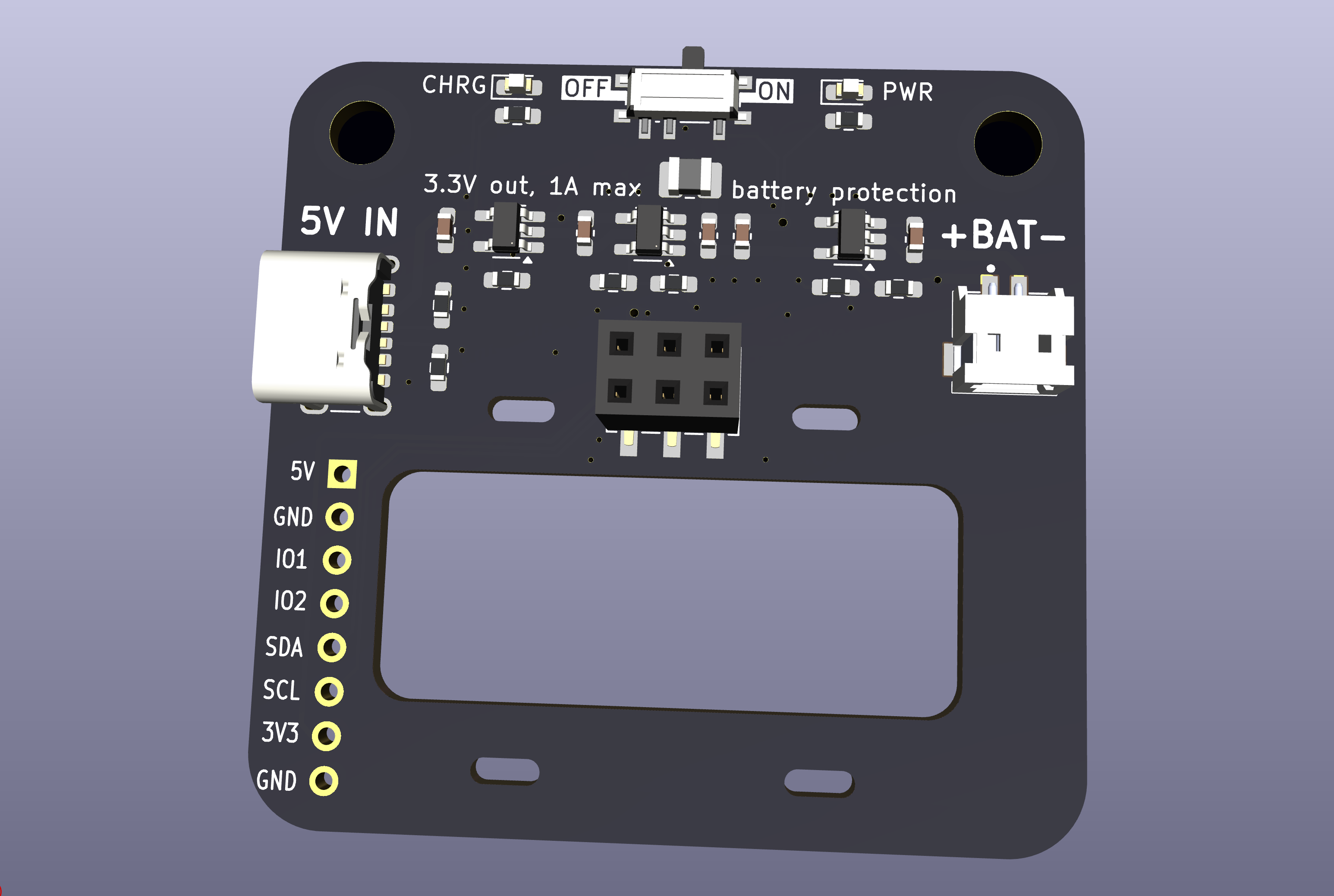
2 layers48 × 46 mmSao vapeorwear, the printed circuit board in 3D

Wearable SAO power pack

Size
48 × 46 mm
Copper layers
2
Thickness
1.6 mm
Parts
26
Nets
21
Pads
86
Tracks, vias
194, 38
Pours
4
Routed
Yes
KiCad
KiCad 10.0 (file 20260206)
Created
26 Apr 2026
Updated
25 May 2026

Overview

Sao vapeorwear is an open-source printed circuit board by exclamationMarek, from the exclamationMarek/vapeorwear repository on GitHub. It is a 2-layer board of 48 × 46 mm with 26 parts on 21 nets, routed with 194 tracks and 38 vias.

It is built around the MT3406 and RY2201. Its parts include 9 resistors, 5 capacitors, 3 ICs, 3 connectors and 2 diodes.

Main components

2

README

README.md

VAPEorWEAR

Wearable SAO power pack

Designed around a battery, that is upcycled from a single use vape, that a friend of mine found (in worryingly large quantities) in the recycling room of his house. It features a proper battery charger and protection IC, so that the poor, abused lithium cell can now live a comfortable afterlife powering your shitty add ons!

Features

  • 400mAh upcycled battery that might smell like fruity vape juice
  • Regulated 3.3V output, 1A max, with short circuit protection
  • 2x M4 holes that should fit lanyard clips
  • Rounded edges and no poking-out THT pins on the backside, to not ruin your nice t-shirt
  • Battery protection and charging from USB
  • On-Off switch (with a <3µA shutdown current)

Kit content

If you received a kit, it should contain:

  • 1x PCB
  • 1x Up-cycled battery. It may smell fruity and be a bit sticky. I attempted to wash it.
  • 3x Different ICs in SOT-23. Don't confuse which one is which!
  • 1x USB connector
  • 1x sliding switch
  • 1x battery connector
  • 1x SAO connector
  • 1x 4.7uH inductor in 1008 package
  • 1x 21k resistor
  • 2x 1uF capacitor
  • 3x 10uF capacitor
  • 4x 560ohm resistor
  • 5x 4.7k resistor

Assembly instruction

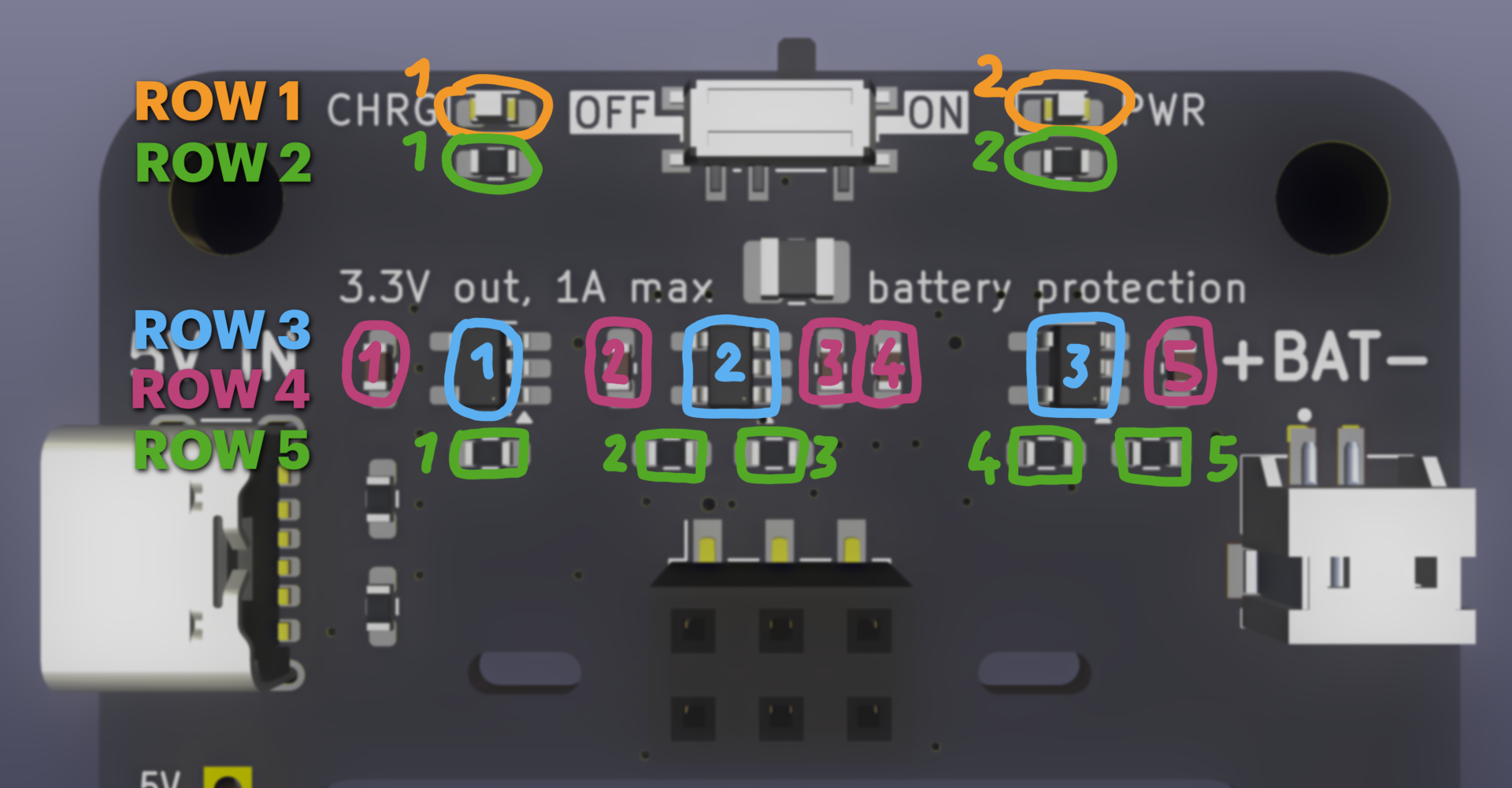
For your convenience, most components are arranged in simple rows. The recommended order of soldering is row by row, and each row is listed from left to right

ROW 1: LEDS

Negative (stripe) always faces left

  1. White LED (charging indicator)
  2. White LED (power indicator)

ROW 2: LED resistors

  1. 560R (sets brightness of charging LED)
  2. 560R (sets brightness of power LED) You can swap them for 4.7k ones if you want the LEDs dimmer

ROW 3: ICs

Pin 1 (dot) is always bottom right

  1. BRCL4054CME (battery charger). Package marking: "4054C"
  2. MT3406 (buck converter). Package marking: "A1xx" (example: A15a)
  3. RY2201 (battery protection). Package marking: "MKxxx" (example: MKJ3L)

ROW 4: Capacitors

  1. 1uF (bypass for charger)
  2. 10uF (bypass for buck)
  3. 10uF (output for buck)
  4. 10uF (more output for buck, optional)
  5. 1uF (bypass for protection IC)

ROW 5: Resistors

  1. 4.7k (charge current set resistor. 4.7k->212mA, 2k->500mA, 10k->100mA)
  2. 4.7k (VOUT set resistor LOW)
  3. 21k (VOUT set resistor HIGH. Included combination results in 3.24V out)
  4. 4.7k (Buck converter ENABLE pull-up). Can be pretty much any value.
  5. 560R (Battery protection IC power filter)

Remaining components:

Their position and orientation has been left as an exercise to the assembler

  1. 4.7uH inductor for the buck converter
  2. On-off switch
  3. Battery connector
  4. USB-C port
  5. 2x 4.7k resistors near the USB-C port (yeah I know these are supposed to be 5.1k but I din't have those on a spool so this is what you get in the kit. Since it's a 1% one, It's stil in the 10% tollerance allowed for the 5.1k by the USB spec so as blasmphemous as this is, it should work)
  6. SAO connector. Unkeyed, sorry!

Post assembly test

  1. Do not plug in battery yet!
  2. Plug in USB power source and test if VBAT reads approx. 4.2V
    • The charge LED is allowed to blink erratically
  3. Turn the switch ON and check if 3.3V out reads approx 3.3V
  4. Check polarity of battery cable. Compare it with the print on the silkscreen
  5. If so, you can unplug the usb, plug in the battery and enjoy your VAPEorWEAR

Design details

RY2201 battery protection IC

  • Overcharge protection at 4.3V
  • Overdischarge protection at 2.4V
  • Overcurrent protection at 3.0A

BRCL4054CME battery charger IC

  • CCCV charging to 4.2V
  • R11 sets charging current. Recommended 4.99k gives 200mA (2.5h charge time)
  • For fastest allowed charging (500mA) use 2k resistor instead.
  • CHRG led will shine during charging, and gently glow when done

MT3406 buck converter

  • Efficiently produces 3.3V from VBAT
  • 1A output continuous, 2A self-protected limit
  • Paired with INPAQ WIP252012P-4R7ML inductor (4.7µH, 1.9A ISat, 196mΩ)
  • Not a boost-buck, so output voltage will start dropping as VBAT drops below 3.4V

ON/OFF switch and PWR LED

  • Switch controls the ENABLE pin of the buck converter
  • LED is connected to the output 3.3V rail
  • Quiescent current when OFF < 3µA
  • Quiescent current when ON approx. 1.2mA, mostly due to the power LED

USB-C port for 5V input

31 x 13mm battery cavity

  • With 4x 3x1.5mm zip-tie or tape slots for mounting
  • Prominently shows the battery, no mechanical cell protection offered
  • JST-ZH (1.5mm) 2-pin connector

2.54mm pin row for connecting to the SAO

  • breaks out all SAO pins, and 5V and extra GND
  • VCC, GND and I2C pins are arranged so that an I2C OLED (example SSD1306) can be connected directly, should the SAO feature a micro and wish to display something.

Other notes

The component values are a bit funky, since they are heavily consolidated for making convinient kits. If you are assembling this with access to a full selection of passives, pick better values. The KiCad design files contain more recommended values.

Parts

26
QtyValueFootprintReferences
310uFCapacitor_SMD:C_0603_1608Metric_Pad1.08x0.95mm_HandSolderC1, C2, C3
32.2kResistor_SMD:R_0603_1608Metric_Pad0.98x0.95mm_HandSolderR4, R11, R14
24.7kResistor_SMD:R_0603_1608Metric_Pad0.98x0.95mm_HandSolderR2, R3
25.1kResistor_SMD:R_0603_1608Metric_Pad0.98x0.95mm_HandSolderR9, R10
2LEDLED_SMD:LED_0603_1608Metric_Pad1.05x0.95mm_HandSolderD1, D2
1100nFCapacitor_SMD:C_0603_1608Metric_Pad1.08x0.95mm_HandSolderC9
11kResistor_SMD:R_0603_1608Metric_Pad0.98x0.95mm_HandSolderR15
11uFCapacitor_SMD:C_0603_1608Metric_Pad1.08x0.95mm_HandSolderC6
122kResistor_SMD:R_0603_1608Metric_Pad0.98x0.95mm_HandSolderR1
14.7uHInductor_SMD:L_1008_2520Metric_Pad1.43x2.20mm_HandSolderL1
1Conn_01x02_MountingPinMareks_footprints:JST_ZH_S2B_1x02_HORIZONTALJ2
1Conn_01x08_PinConnector_PinHeader_2.54mm:PinHeader_1x08_P2.54mm_VerticalJ4
1LOGOLOGOG***
1MT3406Package_TO_SOT_SMD:SOT-23-5_HandSolderingU1
1RY2201Package_TO_SOT_SMD:SOT-23-5_HandSolderingU4
1SW_SPDTButton_Switch_SMD:SW_SPDT_PCM12SW1
1Simple_Addon_v2Connector_PinSocket_2.54mm:PinSocket_2x03_P2.54mm_Vertical_SMDX1
1USB_C_Receptacle_PowerOnly_6PConnector_USB:USB_C_Receptacle_GCT_USB4125-xx-x-0190_6P_TopMnt_HorizontalJ1
1any4054Package_TO_SOT_SMD:SOT-23-5_HandSolderingU2

Similar boards

  • 2 layers38.1 × 50.8 mmSAO Demo Controller, the printed circuit board in 3D

    SAO Demo Controller

    ageppert/SAO_Demo_Controller

    A small inline SAO with an RP2040 used to demo SAOs that require smarts, but don't have it built-in.

    59 parts3
  • 4 layers90 × 10.5 mmUSB Oscilloscope, the printed circuit board in 3D

    USB Oscilloscope

    aroerina/open-pen-type-oscilloscope

    Open pen type oscilloscope

    113 parts13
  • 6 layers44.5 × 36 mmDefcon-34-v3, the printed circuit board in 3D

    Defcon-34-v3

    bunnie/dc34-core-hw

    Core module hardware design

    187 parts10CERN-OHL-W-2.0
  • 2 layers21 × 67.5 mmDabao v3c sdcard, the printed circuit board in 3D

    Dabao v3c sdcard

    Supermagnum/Galdralag-firmware

    A cryptographic framework for Baochip-1x .

    44 parts3GPL-3.0
  • 2 layers19.1 × 21.8 mmEsp32c5-airunit nano, the printed circuit board in 3D

    Esp32c5-airunit nano

    us3r-d0e5nt-3x1st/esp32c5-airunit-nano

    air-unit based on esp32c5-wroom-1u and ov5640, made for the hx-esp32-cam-fpv project, supports both digital video with osd and rc control

    24 parts3
  • 4 layers93.5 × 81 mmUM Controller, the printed circuit board in 3D

    UM Controller

    Aptustech/Micromanipulator_uM_NG

    Next generation Micromanipulator controller

    173 parts2
  • 4 layers214.7 × 90.3 mmKAKATA RC433 V1, the printed circuit board in 3D

    KAKATA RC433 V1

    ArmanyO/ARMANY_ORTEGA_MICRO_CONTROLADORES_2026_C2

    90 partsMIT
  • 2 layers55.8 × 66.5 mmTadpoleswadge, the printed circuit board in 3D

    Tadpoleswadge

    cnlohr/cnhardware

    My dumping grounds for all my kicad projects and random hardware bringup.

    86 parts114

Questions

How big is the Sao vapeorwear PCB?

It measures 48 × 46 mm and has 2 copper layers, 1.6 mm thick.

What parts does the Sao vapeorwear use?

26 parts, built around the MT3406 and RY2201. The full list of its parts is on this page, with links to each part's symbol and footprint where PCBKit's library has them.

Where can I download the Sao vapeorwear KiCad files?

From the exclamationMarek/vapeorwear repository on GitHub, at the commit this page was made from: the board is pcb/sao_vapeorwear.kicad_pcb and its schematic pcb/sao_vapeorwear.kicad_sch. PCBKit opens the board in the browser, with nothing to install.

Can I use the Sao vapeorwear design in my own project?

Its repository states no licence, so its author keeps all rights: ask exclamationMarek before reusing the design.