Skip to the content
PCBKitNew board
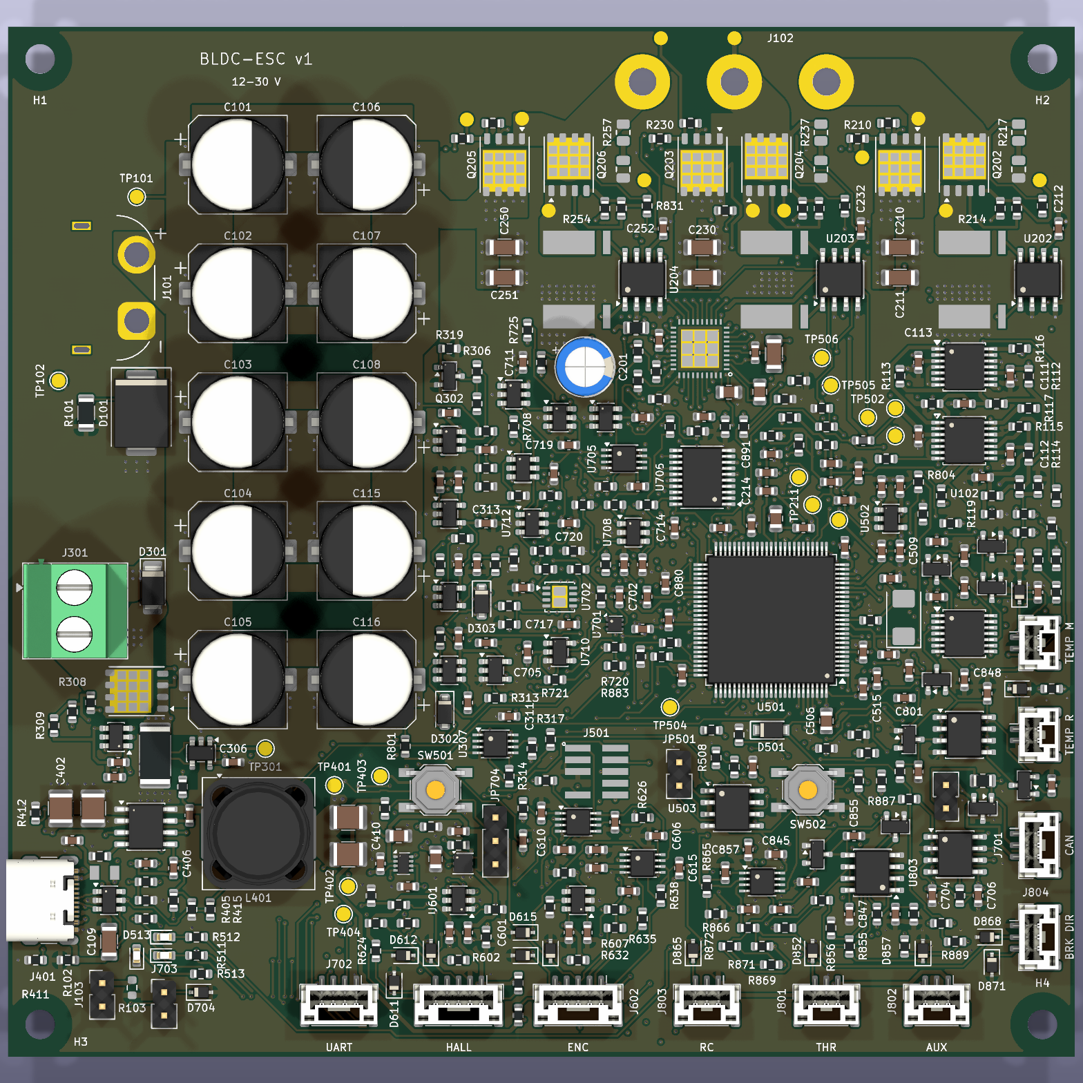
4 layers116 × 112 mmBldc esc, the printed circuit board in 3D

A custom STM32 motor controller for BLDC and PMSM motors.

Size
116 × 112 mm
Copper layers
4
Thickness
1.6 mm
Parts
453
Nets
260
Pads
1,473
Tracks, vias
7,009, 1,557
Pours
37
Routed
Yes
KiCad
KiCad 10.0 (file 20260206)
Created
27 Sep 2026
Updated
11 Oct 2026

Overview

Bldc esc is an open-source printed circuit board by EwoudVV, from the EwoudVV/bldc-esc repository on GitHub. It is a 4-layer board of 116 × 112 mm with 453 parts on 260 nets, routed with 7,009 tracks and 1,557 vias.

It is built around the SN74LVC3G17DCTR, TLV9062IDR-MS and SN74LVC1G11DBVR(AT), with the REF2025AIDDCR, TPS2553DBVR-1 and RC0603FR-0710KL among its other parts. Its parts include 173 resistors, 139 capacitors, 24 diodes, 22 ICs and 8 transistors. It belongs with the robots and motor control boards of this library.

Main components

12

README

README.md

BLDC ESC

i'm building a small vesc like controller for BLDC and PMSM motors. the first motor is a 26V Groschopp gearmotor, but i want the board to be useful for other motors too. Hall control first, then FOC later

PCB render

status

the PCB is fully routed on four copper layers. it's 116 x 112 mm, with 449 component footprints on top and four mounting holes. the fitted BOM has 414 components across 110 different part numbers. KiCad reports zero DRC violations, zero open connections and no schematic mismatches. ERC is clean too

inner logic routing uses a 0.127 mm minimum. some control routes share the inner ground layer, and its filled ground pour stays connected. the USB pair has a continuous ground reference along its bottom-layer path, apart from the via transitions

the mounting holes, fabrication files and first bring-up firmware are done. PCBWay has the board and stencil files for review. the board hasn't been built, powered or tested. the final stack, USB impedance, cooling and some part availability still need checking before ordering

don't manufacture the devlog 03 snapshot (dcad1e4). the XT60 connections were backwards in that version. the current design has pad 1 as GND and pad 2 as VBUS

devlogs are on Half Life and synced to JOURNAL.md

hardware

  • STM32G474VET6 and DRV8353S gate driver
  • six 60V bridge MOSFETs and three 1 milliohm current shunts
  • INA241 current sensing, voltage sensing and temperature inputs
  • hardware current protection, watchdog and brake chopper
  • Hall and encoder inputs, analog throttle, RC PWM and digital controls
  • CAN FD, UART, USB-C and SWD
  • XT60 power input, MT60 motor pigtail and JST-GH signal connectors

targets

  • 12-30V input, mainly for 6S batteries and 24V systems
  • 15A RMS phase current with passive cooling, 20A with extra cooling
  • around 40A peak, with the allowed duration still to be worked out
  • four layers, with 2 oz outer copper and 1 oz inner copper planned; exact stack pending PCBWay review

these current ratings are targets until thermal testing is done

test motor

Groschopp / Blue-White BL6560-PS2120, P/N 930-23-9002:

  • 26V, 0.75A nameplate
  • 10W reducer output, 125 RPM, 6.68 in-lb torque
  • 20:1 gearbox
  • three phase leads and a separate sensor wire bundle

the OEM sensor pinout and motor measurements still need checking

files

  • bldc-esc.kicad_pro: open this in KiCad
  • schematic/: the circuit sheets
  • bldc-esc.kicad_sym and bldc-esc.pretty/: local symbols and footprints
  • bom.csv: component list, including the DNP flags

mounting and assembly

there are four 3.2 mm non-plated holes for M3 mounting, on a 109 x 105 mm rectangle. each hole has a 7 mm copper keepout on every copper layer. use screw heads no larger than 6.4 mm and check the standoff clearance before fitting the board

the plan is to assemble one board myself at the makerspace with a stencil and reflow equipment. the top-only stencil is 0.10 mm thick and frameless. its paste file leaves out the seven DNP parts and keeps the segmented thermal-pad apertures. this is my first board with this kind of assembly, so i'll get help checking the paste and joints before powering it

firmware

firmware/BUILD.md has the build instructions, programming connections and UART commands. the first build can report input states and ADC readings, and read the gate driver's registers. ARM, all six PWM outputs and brake PWM stay low. the gate driver can only wake for register reads when the bus checks pass

the firmware builds for the STM32G474VET6. all three host tests passed, covering commands and measurements, reset outputs and UART input handling. it hasn't been flashed to a board. USB, CAN, motor commutation and FOC are still to come

parts and fabrication

the full purchasing BOM has every part number, fitted and order quantities, vendor links, quotes and availability notes. the purchasing CSV is the same detailed parts list in spreadsheet form. BOM.md is the grouped list synced from Half Life

quotes checked on October 11: five bare PCBWay boards are $311.90, the stencil is $10, and the component merchandise estimate is $191.29 before shipping, tax and discounts. the component figure includes backorders and unconfirmed offers. 100 of the 110 part numbers had confirmed stock; ten still need a source or delivery confirmation

the website list is $543.92 with its current shipping and tariff allowance. that is still an estimate, not a final checkout total. the full BOM explains the discounts, missing shipping quotes and difference from the supplier carts. nothing has been paid for. submission is paused while the over-budget form issue is sorted out

before ordering, PCBWay needs to confirm the 2 oz outer / 1 oz inner copper stack, layer-specific routing limits, small vias and 90 ohm USB pair. the quote form forces 8 mil globally even though the inner routing is 0.127 mm. the uploaded notes give the actual geometry, and a price and impedance review is pending

manufacturing files

Parts

453
QtyValueFootprintReferences
48100n 50VCapacitor_SMD:C_0603_1608MetricC113, C114, C207, C212, C232, C252, C302, C303, C304, C306, C307, C309, C311, C313, C413, C501 +32
3810kResistor_SMD:R_0603_1608MetricR117, R203, R205, R311, R312, R313, R407, R410, R415, R504, R505, R508, R603, R607, R621, R624 +22
201kResistor_SMD:R_0603_1608MetricR216, R236, R256, R501, R511, R512, R513, R620, R623, R626, R632, R635, R638, R709, R721, R865 +4
191n 50VCapacitor_SMD:C_0603_1608MetricC213, C214, C233, C234, C253, C254, C301, C308, C802, C812, C822, C832, C852, C857, C865, C868 +3
17100kResistor_SMD:R_0603_1608MetricR204, R314, R315, R317, R319, R402, R409, R503, R602, R606, R704, R705, R707, R708, R716, R724 +1
1710k 0.1%Resistor_SMD:R_0603_1608MetricR110, R113, R114, R119, R304, R320, R418, R803, R813, R823, R833, R880, R883, R886, R889, R898 +1
14PESD5V0S1BADiode_SMD:D_SOD-323D610, D611, D612, D613, D614, D615, D704, D852, D857, D865, D868, D871, D888, D891
1310n 50VCapacitor_SMD:C_0603_1608MetricC110, C111, C112, C117, C310, C705, C850, C855, C880, C883, C886, C889, C899
11100Resistor_SMD:R_0603_1608MetricR215, R235, R255, R804, R814, R824, R834, R852, R857, R888, R891
11100k 0.1%Resistor_SMD:R_0603_1608MetricR301, R302, R405, R801, R802, R811, R812, R821, R822, R831, R832
10100u 63VCapacitor_SMD:CP_Elec_10x12.5C101, C102, C103, C104, C105, C106, C107, C108, C115, C116
101u 16VCapacitor_SMD:C_0603_1608MetricC206, C305, C314, C408, C409, C411, C510, C602, C604, C706
8BAV199Package_TO_SOT_SMD:SOT-23D801, D811, D821, D831, D850, D855, D886, D889
7100p 50VCapacitor_SMD:C_0603_1608MetricC312, C610, C611, C612, C613, C614, C615
747kResistor_SMD:R_0603_1608MetricR211, R213, R231, R233, R251, R253, R309
7ISC011N06LM5Package_SON:Infineon_PG-TDSON-8_6.15x5.15mmQ201, Q202, Q203, Q204, Q205, Q206, Q301
61u 100VCapacitor_SMD:C_1206_3216MetricC210, C211, C230, C231, C250, C251
63.3Resistor_SMD:R_0603_1608MetricR210, R212, R230, R232, R250, R252
6SN74LVC1G11DBVRPackage_TO_SOT_SMD:SOT-23-6U703, U704, U707, U708, U711, U712
54.7kResistor_SMD:R_0603_1608MetricR116, R202, R306, R506, R507
40Resistor_SMD:R_0603_1608MetricR103, R502, R701, R703
4220p 50VCapacitor_SMD:C_0603_1608MetricC801, C811, C821, C831
44.7u 25VCapacitor_SMD:C_0805_2012MetricC410, C412, C506, C507
4MountingHole_3.2mm_M3MountingHole_3.2mm_M3H1, H2, H3, H4
310Resistor_SMD:R_0805_2012MetricR217, R237, R257
31m 1% 8Wbldc-esc:CSS4J_4026R214, R234, R254
31n 100VCapacitor_SMD:C_0805_2012MetricC215, C235, C255
3INA241A2IDRPackage_SO:SOIC-8_3.9x4.9mm_P1.27mmU202, U203, U204
3SN74LVC3G17DCTRPackage_SO:SSOP-8_2.95x2.8mm_P0.65mmU603, U604, U802
210k / B25-50=3380KResistor_SMD:R_0603_1608MetricTH801, TH802
212.1kResistor_SMD:R_0603_1608MetricR850, R855
2150kResistor_SMD:R_0603_1608MetricR316, R318
22.2n 50VCapacitor_SMD:C_0603_1608MetricC403, C406
22.2u 100VCapacitor_SMD:C_1210_3225MetricC401, C402
2200kResistor_SMD:R_0603_1608MetricR601, R605
222Resistor_SMD:R_0603_1608MetricR413, R414
222u 25VCapacitor_SMD:C_1210_3225MetricC404, C405
227p 50VCapacitor_SMD:C_0603_1608MetricC513, C514
2300kResistor_SMD:R_0603_1608MetricR401, R408
25.1kResistor_SMD:R_0603_1608MetricR411, R412
290.9k 0.1%Resistor_SMD:R_0603_1608MetricR111, R112
2BAT54HDiode_SMD:D_SOD-123FD302, D303
2GNDTestPoint:TestPoint_Pad_D1.5mmTP102, TP404
2REF2025AIDDCRPackage_TO_SOT_SMD:SOT-23-5U308, U502
2SN74LVC1G74DCTRPackage_SO:SSOP-8_2.95x2.8mm_P0.65mmU307, U705
2TLV9024PWRPackage_SO:TSSOP-14_4.4x5mm_P0.65mmU101, U102
2TLV9062IDRPackage_SO:SOIC-8_3.9x4.9mm_P1.27mmU803, U804
2TPS2553DBVR-1Package_TO_SOT_SMD:SOT-23-6U601, U602
10.5A / 6Vbldc-esc:MF_PSMF0805F401
11Resistor_SMD:R_0603_1608MetricR308
1100n 100VCapacitor_SMD:C_0603_1608MetricC202
110kResistor_SMD:R_1206_3216MetricR101
1120Resistor_SMD:R_0805_2012MetricR719
115kResistor_SMD:R_0603_1608MetricR416
115k 0.1%Resistor_SMD:R_0603_1608MetricR321
116.9k 0.1%Resistor_SMD:R_0603_1608MetricR115
11MResistor_SMD:R_0603_1608MetricR102
11u 25VCapacitor_SMD:C_0805_2012MetricC205
11u 50VCapacitor_SMD:C_1206_3216MetricC204
12.2Resistor_SMD:R_0603_1608MetricR307
12.2Resistor_SMD:R_0805_2012MetricR201
12.49MResistor_SMD:R_0603_1608MetricR305
122u 63VCapacitor_THT:CP_Radial_D6.3mm_P2.50mmC201
12N7002Package_TO_SOT_SMD:SOT-23Q302
1301kResistor_SMD:R_0603_1608MetricR406
1324k 0.1%Resistor_SMD:R_0603_1608MetricR404
13V3TestPoint:TestPoint_Pad_D1.5mmTP403
13V3_ATestPoint:TestPoint_Pad_D1.5mmTP503
13m / 3WResistor_SMD:R_2512_6332MetricR310
14.7n 1kVCapacitor_SMD:C_1206_3216MetricC109
140.2k 0.1%Resistor_SMD:R_0603_1608MetricR118
142.2kResistor_SMD:R_0603_1608MetricR403
147n 100VCapacitor_SMD:C_0805_2012MetricC203
147n 50VCapacitor_SMD:C_0603_1608MetricC702
151.1k 0.1%Resistor_SMD:R_0603_1608MetricR417
15V_BUSTestPoint:TestPoint_Pad_D1.5mmTP401
15V_SYSTestPoint:TestPoint_Pad_D1.5mmTP402
1600R @ 100MHzInductor_SMD:L_0603_1608MetricFB501
168uH / Isat>=2.3AInductor_SMD:L_Coilcraft_MSS1246T-XXXL401
18.45k 0.1%Resistor_SMD:R_0603_1608MetricR303

The 381 most common of 453 parts.

Questions

How big is the Bldc esc PCB?

It measures 116 × 112 mm and has 4 copper layers, 1.6 mm thick.

What parts does the Bldc esc use?

453 parts, built around the SN74LVC3G17DCTR, TLV9062IDR-MS, SN74LVC1G11DBVR(AT) and REF2025AIDDCR. The full list of its parts is on this page, with links to each part's symbol and footprint where PCBKit's library has them.

Where can I download the Bldc esc KiCad files?

From the EwoudVV/bldc-esc repository on GitHub, at the commit this page was made from: the board is bldc-esc.kicad_pcb and its schematic bldc-esc.kicad_sch. PCBKit opens the board in the browser, with nothing to install.

Can I use the Bldc esc design in my own project?

Its repository states no licence, so its author keeps all rights: ask EwoudVV before reusing the design.

Similar boards

  • 6 layers76.8 × 67 mmBLDC motor controller, the printed circuit board in 3D

    BLDC motor controller

    Ricsi1231/BLDC-motor-controller-Hardware---HDI-Desing

    EmbedCore motor controller is a high-power brushless motor controller. It was specifically designed to be integrated in Autonomus Mobile Robot wheel actuators. Motor controller can be intagreted to other applications.

    383 parts1Apache-2.0
  • 2 layers101 × 82 mmPower board v4 4, the printed circuit board in 3D

    Power board v4 4

    maurer-lbb/inkube_hardware

    Open-source hardware (CAD + PCB) for inkudock, a modular incubator and closed-loop electrophysiology, and a water compartment lid preventing evaporation from cell cultures.

    117 parts
  • 2 layers210 × 160 mmRF80, the printed circuit board in 3D

    RF80

    DD1SB/ARDF-TX

    Date: 2026-10-15. Engineering review only; unbuilt and unenergized. Open RF80.kicadpro, schematic and native PCB in KiCad10.0.6. Three primary PCBs and the separate VHF true-AM design are unchanged.

    277 partsMIT
  • 2 layers72.2 × 33.9 mmBoostUnit, the printed circuit board in 3D

    BoostUnit

    senrobo/open

     . │ ├──  l1 │ ├──  3dmodels │ │ ├──  .DSStore │ │ ├──  0603Inductor.step │ │ ├──  1040Inductor.step │ │ ├──  ALS-PT19.step │ │ ├──  C0603.step │ │ ├──  CAPPRD750W80D1600H2500.stp │ │ ├──  CD74HC4067M.step │ │…

    26 partsMIT
  • 2 layers100 × 100 mmEarth Field NMR, the printed circuit board in 3D

    Earth Field NMR

    fmarrabal/Earth-Field-NMR

    This repository contains the complete design, schematics, PCB layout, microcontroller firmware, and computer software for an Earth Field Nuclear Magnetic Resonance (EFNMR) spectrometer.

    103 parts5MIT
  • 4 layers154 × 81 mmSystem candidate, the printed circuit board in 3D

    System candidate

    bernardopg/ps28-modern-amp

    Infinity Primus PS28 amplifier modernization: TPA3255 engineering, validation and safety-gated workflow

    269 parts1
  • 4 layers90 × 70 mmRobot hub rev3, the printed circuit board in 3D

    Robot hub rev3

    dustin-lehmann/TWIPR

    See https://github.com/dustin-lehmann/TWIPR/wiki for descriptions on how to use the hardware and software

    278 parts1