2 layers73 × 94 mm
Sportiduino base
sportiduino/sportiduino
Electronic timing system for orienteering and similar outdoor sports events on Arduino
119 parts78GPL-3.0

 evan-loe/atmega-power-hat
And thats it! Your hat should be ready to use
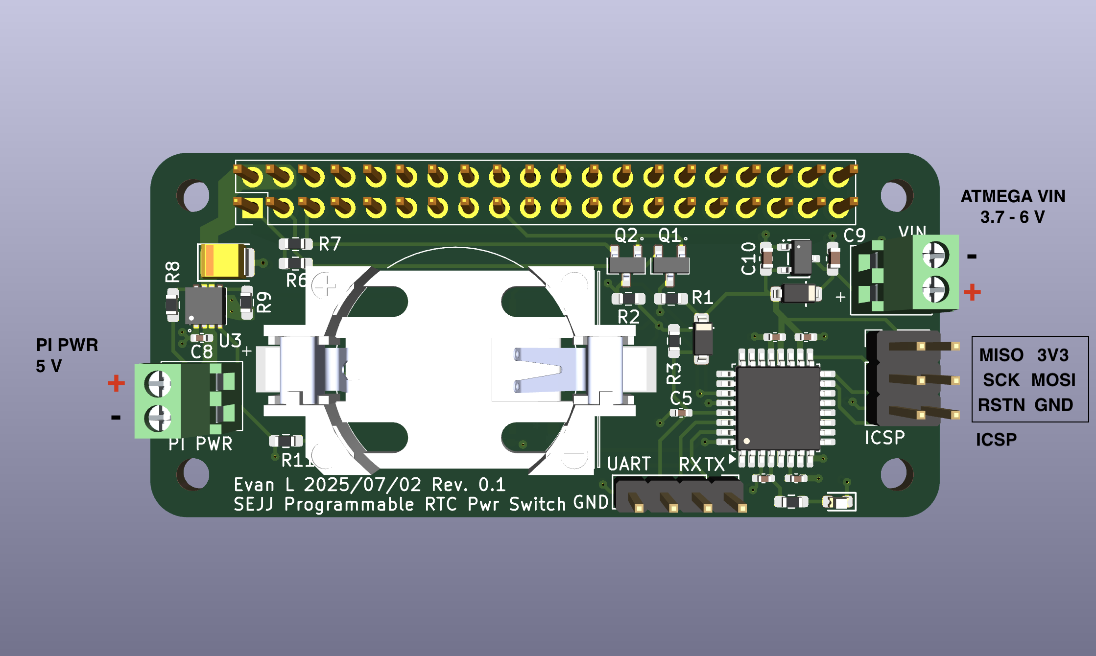
ATMEGA Power Circuit is an open-source printed circuit board by evan-loe, from the evan-loe/atmega-power-hat repository on GitHub. It is a 4-layer board of 65 × 30 mm with 40 parts on 63 nets, routed with 261 tracks and 44 vias.
It is built around the ATMEGA328P-AU, XC6206P332MR and DS3231SN#T&R, with the BSS138 and CR2032 among its other parts. Its parts include 11 resistors, 10 capacitors, 4 ICs, 3 diodes and 3 connectors. It belongs with the AVR (ATmega, ATtiny) boards of this library.


The ATMEGA Power Hat is an RTC enabled Raspberry Pi compatible HAT (Hardware-Attached-on-Top) that can automatically wakeup and shutdown the pi on a given schedule.
configure_i2c_rtc.shbuild/ to flash the firmware onto the ATEMGA using your ISP and programs such as Microchip Studio or AVRDude.E2 D9 FF0xE2 to enable internal clock running at 8 MHzAnd thats it! Your hat should be ready to use
The source code of the firmware is available in power.cpp. It was developed using the Arduino v2.3.6 libararies.
The code does the following when powered ON:
0x20.While waiting for successful boot
Boot Success I2C commandAfter receiving the Boot Success signal
Shutdown commandWhen the Shutdown command is received
Boot Success command to be sent from the PI.The ATMEGA does not program the RTC over i2c.
The following section describes the transaction format recognized by the ATMEGA. The first byte denotes the command type, and the second byte denotes the value if applicable.
The Base Address of the ATMEGA is 0x20
| Command | First Byte (txn_type) | Second Byte (data) | Description | Action |
|---|---|---|---|---|
| Shutdown | 0x00 | 0x00-0xFF | Shutdown command | Sets shutdown_in variable to data value |
| Boot Success | 0x01 | Any value | Boot success signal | Sets successful_boot flag to 1 |
Since any data is encoded in a single byte, the max delay from receiving the i2c signal to cutting power is 2^8=256 seconds.
The CAD files can be found in the ATMegaPowerCircuit folder.
Select the Aruduino UNO as your device. Paste power.cpp into your Arduino IDE and click Sketch > Export Compiled Binary
RTC lib docs: https://adafruit.github.io/RTClib/html/index.html (We are using the DS3231 RTC chip)
| Qty | Value | Footprint | References |
|---|---|---|---|
| 7 | 100n | Capacitor_SMD:C_0402_1005Metric_Pad0.74x0.62mm_HandSolder | C1, C2, C3, C4, C5, C6, C8 |
| 4 | 10K | Resistor_SMD:R_0603_1608Metric_Pad0.98x0.95mm_HandSolder | R6, R7, R10, R11 |
| 4 | MountingHole | MountingHole:MountingHole_2.7mm_M2.5 | H1, H2, H3, H4 |
| 3 | 4k7 | Resistor_SMD:R_0603_1608Metric_Pad0.98x0.95mm_HandSolder | R1, R2, R4 |
| 2 | 1.0 uf | Capacitor_SMD:C_0603_1608Metric_Pad1.08x0.95mm_HandSolder | C9, C10 |
| 2 | B5819W SL | PCM_JLCPCB:D_SOD-123 | D1, D2 |
| 2 | BSS138 | BSS138:SOT95P240X111-3N | Q1, Q2 |
| 2 | Screw_Terminal_01x02 | Weurth_Terminal_01x02_691210910002:691210910002 | J3, J4 |
| 1 | 0 | Jumper:SolderJumper-2_P1.3mm_Open_Pad1.0x1.5mm | R5 |
| 1 | 100k | Resistor_SMD:R_0603_1608Metric_Pad0.98x0.95mm_HandSolder | R8 |
| 1 | 100uF | PCM_JLCPCB:C_CASE-B-3528-21(mm) | C7 |
| 1 | 10k | Resistor_SMD:R_0603_1608Metric_Pad0.98x0.95mm_HandSolder | R3 |
| 1 | 22k1 | Resistor_SMD:R_0603_1608Metric_Pad0.98x0.95mm_HandSolder | R9 |
| 1 | ATmega328P-A | Package_QFP:TQFP-32_7x7mm_P0.8mm | U1 |
| 1 | CR2032 | Battery:BAT-TH_CR2032-BS-6-1 | BT1 |
| 1 | Conn_01x04 | Connector_PinHeader_2.54mm:PinHeader_1x04_P2.54mm_Vertical | UART |
| 1 | ICSP | Connector_PinHeader_2.54mm:PinHeader_2x03_P2.54mm_Vertical | ICSP |
| 1 | Raspberry_Pi_2_3 | Connector_PinHeader_2.54mm:PinHeader_2x20_P2.54mm_Vertical | J5 |
| 1 | Red | PCM_JLCPCB:D_0603 | D3 |
| 1 | TPS2557DRBR | TPS2557DRBR:SON65P300X300X100-9N | U3 |
| 1 | XC6206P332MR | PCM_JLCPCB:SOT-23-3_L2.9-W1.6-P1.90-LS2.8-BR | U4 |
| 1 | ds3231sn- | footprints:21-0042B_16_MXM | U2 |
sportiduino/sportiduino
Electronic timing system for orienteering and similar outdoor sports events on Arduino

ConquerToFreedom/SwasthEdge
Low-cost self-diagnosing edge controller for industrial sensor reliability

hasky00/kizami-core
FPGA side of Kizami — cycle-exact timecode + audio witness on iCE40

Takingo/Mypcb35
OmniCircuit AI is a local proof of concept for an autonomous PCB/PCBA design and manufacturing suite. The current implementation focuses on the ESP32-S3 + DWM3000 UWB Anchor example and establishes the architecture for:

trabem/home_sense_meteostation
Репозиторій автономної battery-powered метеостанції на ESP32-C3-WROOM-02. Містить firmware (ESP-IDF / FreeRTOS), KiCad-проєкти двох плат і матеріали фінальної презентації.

silicagel777/SuperClock
A DIY desk clock with retro-style dot matrix display


It measures 65 × 30 mm and has 4 copper layers, 1.6 mm thick.
40 parts, built around the ATMEGA328P-AU, XC6206P332MR, DS3231SN#T&R and BSS138. The full list of its parts is on this page, with links to each part's symbol and footprint where PCBKit's library has them.
From the evan-loe/atmega-power-hat repository on GitHub, at the commit this page was made from: the board is ATMEGA Power Circuit/ATMEGA Power Circuit.kicad_pcb and its schematic ATMEGA Power Circuit/ATMEGA Power Circuit.kicad_sch. PCBKit opens the board in the browser, with nothing to install.
Its repository states no licence, so its author keeps all rights: ask evan-loe before reusing the design.