Skip to the content
PCBKitNew board
4 layers15.3 × 45.8 mmCurrentSource, the printed circuit board in 3D

This chewing gum board is designed to be an extended-range voltage supply + current measurement circuit, intended for connection to the main board through the male pin headers to both sides.

Size
15.3 × 45.8 mm
Copper layers
4
Thickness
1.61 mm
Parts
39
Nets
31
Pads
129
Tracks, vias
366, 40
Pours
4
Routed
Yes
KiCad
KiCad 9.0 (file 20241229)
Created
22 Dec 2025
Updated
1 May 2026

Overview

CurrentSource is an open-source printed circuit board by esl-epfl, from the esl-epfl/CHEEP-boards repository on GitHub. It is a 4-layer board of 15.3 × 45.8 mm with 39 parts on 31 nets, routed with 366 tracks and 40 vias.

It is built around the ADS1219IPW and TLV75801PDBV. Its parts include 12 resistors, 10 capacitors, 6 ICs, 4 connectors and 1 diode.

Main components

2

README

chewing-gums/ExtendedRangeSupply/README.md

Overview

This chewing gum board is designed to be an extended-range voltage supply + current measurement circuit, intended for connection to the main board through the male pin headers to both sides. It can produce a voltage output from 0 to 5 V approximately, with currents of up to 1 A (@nominal voltage, check datasheet).

User guide and programmability

This chewing gum board is an adaptation of the CurrentMeasurementSupply chewing gum and as such can be used in a similar way, the main difference being the wider supply voltage range. This Extended Range version, however, supports only a single voltage output ("A").

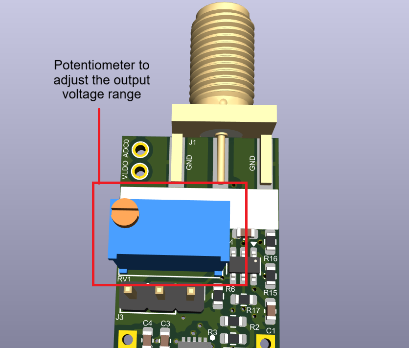
It is based on the TPS7A9401 IC. The output voltage is defined via a resistor network, with a potentiometer soldered to the board that allows to manually modify the output within this range.
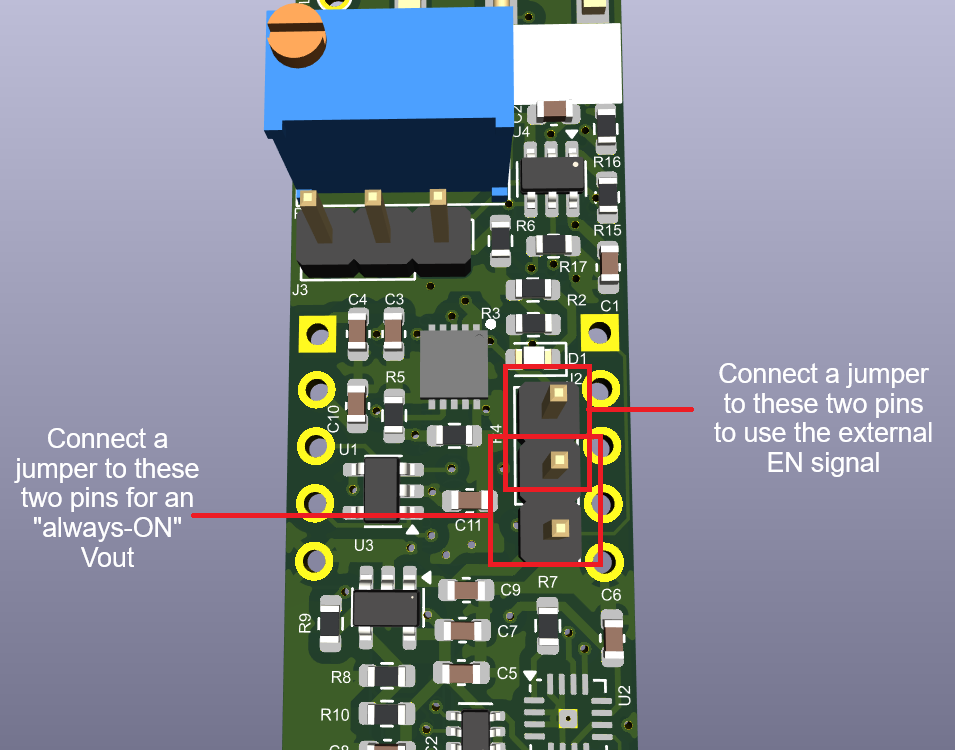
The TPS7A9401 is always ON and will operate when the EN pin is high. Either the external EN input, or the internal supply signal can be used to set the EN pin. This can be selected through the J2 jumper.
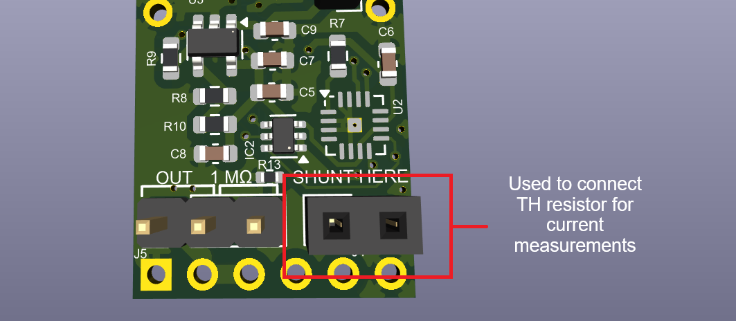
Similar to the CurrentMeasurementSupply chewing gum board, this extended range version can also be use to obtain a reading of the output current. All the current measurement circuits are kept unchanged and therefore can be used in the same way by employing shunt resistors + the ADC reading.

Female pin header J3 can be used to connect a through-hole resistor for current measurement. This allows for quicker replacement of the shunt resistor values, as opposed to the SMD alternatives.
The "VLDO" test point next to the SMA connector can also be used to measure the output voltage.

DAC programming

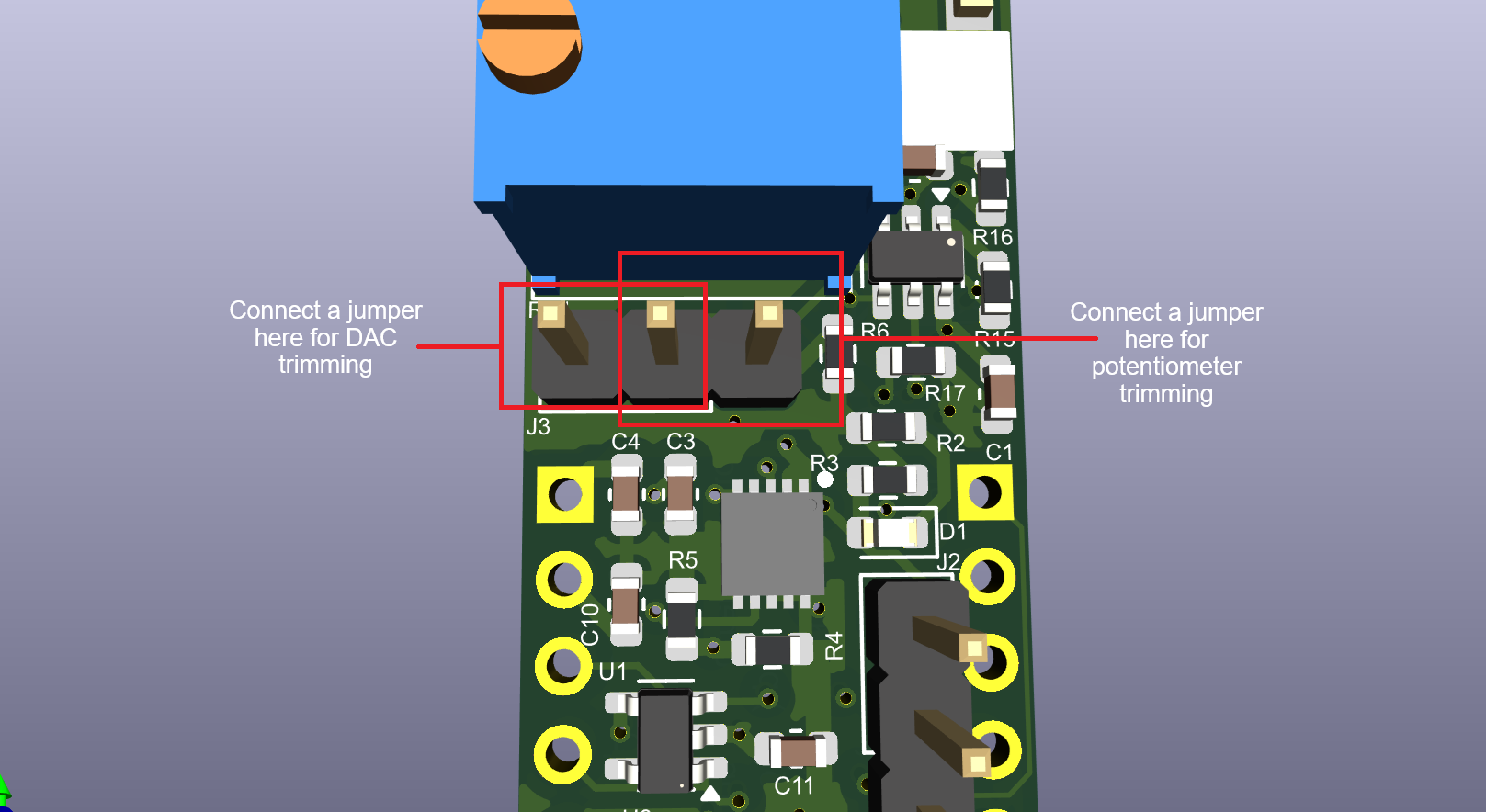
Besides using the potentiometer for trimming, the output voltage can also be adjusted by changing the input to the DAC. For this operation, however, resistors R15 and R16 need to be selected for this by carefully checking the possible voltage range with the datasheet.

Jumper J3 can be used to set potentiometer or DAC trimming.
Simulations

A macromodel of the TPS7A9401, together with a simplified circuit modeling its behavior in this board has been included. The simulation can be run using TINA-TI. This allows, for example, to change resistors and verify the output voltage of the TPS7A9401, as well as the output current when simulating with a load.

Parts

39
QtyValueFootprintReferences
70.1uCapacitor_SMD:C_0603_1608MetricC1, C2, C5, C6, C7, C8, C10
210kResistor_SMD:R_0603_1608MetricR7, R9
2~TestPoint:TestPoint_Loop_D1.80mm_Drill1.0mm_BeadedTP1, TP2
1.1uCapacitor_SMD:C_0603_1608MetricC4
110Resistor_SMD:R_0805_2012Metric_Pad1.20x1.40mm_HandSolderR1
110Resistor_SMD:R_1206_3216Metric_Pad1.30x1.75mm_HandSolderR12
110Resistor_SMD:R_2512_6332Metric_Pad1.40x3.35mm_HandSolderR6
110Resistor_SMD:R_2010_5025Metric_Pad1.40x2.65mm_HandSolderR11
1100kResistor_SMD:R_0603_1608MetricR10
110uCapacitor_SMD:C_0603_1608MetricC3
1140kResistor_SMD:R_0603_1608MetricR3
11MResistor_SMD:R_0402_1005MetricR5
11uCapacitor_SMD:C_0603_1608MetricC9
120kResistor_SMD:R_0603_1608MetricR8
124AA02E-OTPackage_TO_SOT_SMD:SOT-23-5U1
13.3kResistor_SMD:R_0603_1608MetricR4
1500KPotentiometer_THT:Potentiometer_Bourns_3296W_VerticalRV1
175kResistor_SMD:R_0603_1608MetricR2
1ADS1219Package_DFN_QFN:Texas_RTE0016D_WQFN-16-1EP_3x3mm_P0.5mm_EP0.8x0.8mm_ThermalViasU2
1BOARD_CONNECTORheep-footprints:chewing-gum-pcbCG1
1Conn_01x02Connector_PinHeader_2.54mm:PinHeader_1x02_P2.54mm_VerticalJ2
1Conn_01x02Connector_PinSocket_2.54mm:PinSocket_1x02_P2.54mm_VerticalJ3
1Conn_02x01Connector_PinHeader_2.54mm:PinHeader_1x03_P2.54mm_VerticalJ4
1Conn_CoaxialConnector_Coaxial:SMA_Amphenol_132289_EdgeMountJ1
1INA212AIDCKRPackage_TO_SOT_SMD:SOT-363_SC-70-6IC1
1LEDLED_SMD:LED_0603_1608MetricD1
1LM334M_NOPBLM334:SOIC127P600X175-8NIC2
1LOGOheep-footprints:ESL_3x3G***
1LOGOheep-footprints:EPFL_3x1G***
1MCP4726Package_TO_SOT_SMD:TSOT-23-6U4
1TLV75801PDBVPackage_TO_SOT_SMD:SOT-23-5U3

Questions

How big is the CurrentSource PCB?

It measures 15.3 × 45.8 mm and has 4 copper layers, 1.61 mm thick.

What parts does the CurrentSource use?

39 parts, built around the ADS1219IPW and TLV75801PDBV. The full list of its parts is on this page, with links to each part's symbol and footprint where PCBKit's library has them.

Where can I download the CurrentSource KiCad files?

From the esl-epfl/CHEEP-boards repository on GitHub, at the commit this page was made from: the board is chewing-gums/CurrentSource/CurrentSource.kicad_pcb and its schematic chewing-gums/CurrentMeasurementSupply/nA_current_shunt_monitor_gum.kicad_sch. PCBKit opens the board in the browser, with nothing to install.

Can I use the CurrentSource design in my own project?

Its repository states no licence, so its author keeps all rights: ask esl-epfl before reusing the design.

More from esl-epfl/CHEEP-boards

1
  • 4 layers15.3 × 45.8 mmExtendedRangeSupply, the printed circuit board in 3D

    ExtendedRangeSupply

    esl-epfl/CHEEP-boards

    This chewing gum board is designed to be an extended-range voltage supply + current measurement circuit, intended for connection to the main board through the male pin headers to both sides.

    46 parts2

Similar boards

  • 2 layers78.1 × 50.2 mmRMTS, the printed circuit board in 3D

    RMTS

    reilleya/RMTS-Hardware

    DAQ and ignition system for solid rocket motors

    84 parts15
  • 2 layers25 × 25 mmADS1219, the printed circuit board in 3D

    ADS1219

    becauseimclever/BreakoutBoards

    Collection of various SMT breakout boards

    20 parts1MIT
  • 2 layersLCP Controller, the printed circuit board in 3D

    LCP Controller

    NOAA-PMEL/EDD-LCP_Control

    Control PCB & Firmware for Low Cost Profiler

    251 parts1MIT
  • 2 layers63.5 × 82.6 mmADS1219Module, the printed circuit board in 3D

    ADS1219Module

    freudenthal/ADS1219Module

    An ADS1219 I2C module

    92 partsGPL-3.0
  • 2 layers139 × 45 mmSoil Power Sensor, the printed circuit board in 3D

    Soil Power Sensor

    jlab-sensing/ENTS-node-hardware

    Schematics and design for soil MFC voltage and current sensing

    72 parts