
2 layers155.5 × 130 mm
Einkpicframe
Spritetm/picframe_colepd
A WiFi picture frame allowing for remote photo uploads, using an ESP32-C3 and a 5.6" color E-ink display
60 parts97

 esiealab/watto-meter2
Watto-Meter: An open-source USB-C power consumption meter with real-time measurements, data logging, and a web interface for control and monitoring.
Watto meter is an open-source printed circuit board by esiealab, from the esiealab/watto-meter repository on GitHub, published under the MIT licence. It is a 2-layer board of 91.8 × 59.5 mm with 43 parts on 62 nets, routed with 361 tracks and 92 vias.
It is built around the ESP32-C3-WROOM-02-H4. Its parts include 12 resistors, 6 capacitors, 4 connectors, 3 ICs and 3 switches. It belongs with the ESP32 and RISC-V boards of this library.
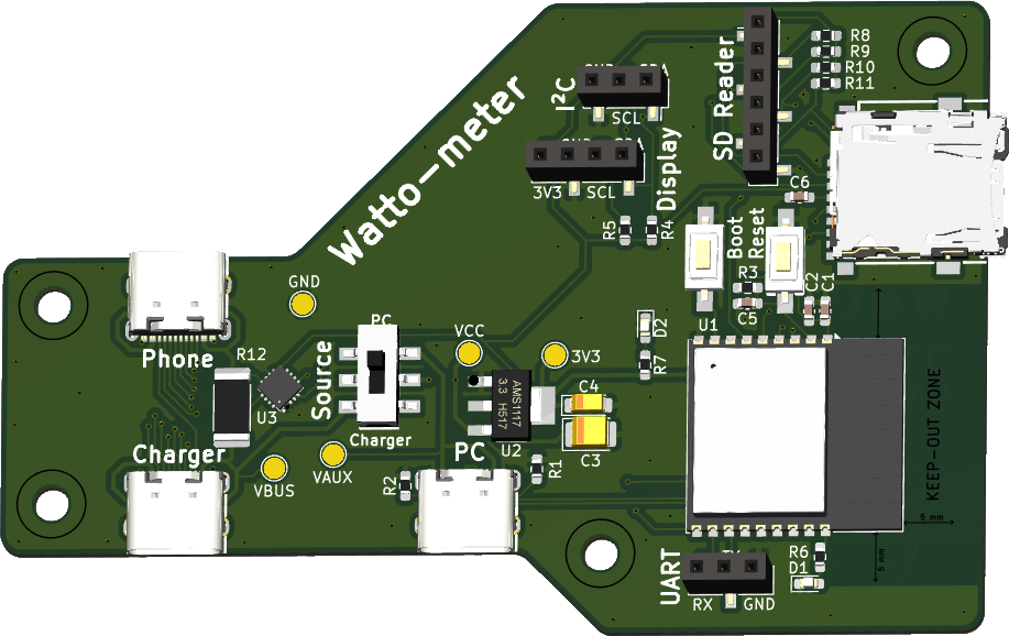
The hardware for Watto-Meter is also open-source, created by @Hyrla. All the files required to manufacture the PCB and assemble the device are available in the hardware/ folder.
Below is an image of the Watto-Meter hardware:
To manufacture the PCB, you can use JLCPCB's fabrication service. Follow these steps:
Download the Gerber files:
hardware/ folder.Create an account on JLCPCB:
Upload the Gerber files:
Configure fabrication options:
Order components:
hardware/production/ folder.Place the order:
| Qty | Value | Footprint | References |
|---|---|---|---|
| 5 | TestPoint | TestPoint:TestPoint_Pad_D2.0mm | TP1, TP2, TP3, TP4, TP5 |
| 4 | DNP | Resistor_SMD:R_0603_1608Metric_Pad0.98x0.95mm_HandSolder | R8, R9, R10, R11 |
| 4 | MountingHole | MountingHole:MountingHole_3.2mm_M3 | H1, H2, H3, H4 |
| 3 | 10k | Resistor_SMD:R_0603_1608Metric_Pad0.98x0.95mm_HandSolder | R3, R4, R5 |
| 3 | ~ | LocalLib:USB-C-SMD_TYPE-C-6PIN-2MD-073 | USB1, USB2, USB3 |
| 2 | 10uF | Capacitor_SMD:C_0603_1608Metric_Pad1.08x0.95mm_HandSolder | C2, C6 |
| 2 | 1k | Resistor_SMD:R_0603_1608Metric_Pad0.98x0.95mm_HandSolder | R6, R7 |
| 2 | 5.1k | Resistor_SMD:R_0603_1608Metric_Pad0.98x0.95mm_HandSolder | R1, R2 |
| 2 | LED | LED_SMD:LED_0603_1608Metric_Pad1.05x0.95mm_HandSolder | D1, D2 |
| 1 | 100nF | Capacitor_SMD:C_0603_1608Metric_Pad1.08x0.95mm_HandSolder | C1 |
| 1 | 10uF | Capacitor_Tantalum_SMD:CP_EIA-3528-21_Kemet-B_Pad1.50x2.35mm_HandSolder | C3 |
| 1 | 1uF | Capacitor_SMD:C_0603_1608Metric_Pad1.08x0.95mm_HandSolder | C5 |
| 1 | 22uF | Capacitor_Tantalum_SMD:CP_EIA-3216-18_Kemet-A_Pad1.58x1.35mm_HandSolder | C4 |
| 1 | 2m | Resistor_SMD:R_2512_6332Metric_Pad1.40x3.35mm_HandSolder | R12 |
| 1 | BOOT | LocalLib:SW-SMD_L6.0-W3.3-LS8.0 | SW3 |
| 1 | Conn_01x04 | Connector_PinSocket_2.54mm:PinSocket_1x04_P2.54mm_Vertical_SMD_Pin1Right | J4 |
| 1 | ESP32-C3-WROOM-02 | RF_Module:ESP32-C3-WROOM-02 | U1 |
| 1 | I2C | Connector_PinSocket_2.54mm:PinSocket_1x03_P2.54mm_Vertical_SMD_Pin1Right | J3 |
| 1 | Micro SD | Connector_PinSocket_2.54mm:PinSocket_1x06_P2.54mm_Vertical_SMD_Pin1Left | J2 |
| 1 | RESET | LocalLib:SW-SMD_L6.0-W3.3-LS8.0 | SW2 |
| 1 | UART | Connector_PinSocket_2.54mm:PinSocket_1x03_P2.54mm_Vertical_SMD_Pin1Right | J1 |
| 1 | ~ | LocalLib:SW-SMD_HOOYA_MS-22D17AG2.5-B | SW1 |
| 1 | ~ | LocalLib:TF-SMD_TF-PUSH | CARD1 |
| 1 | ~ | LocalLib:VQFN-16_L3.0-W3.0-P0.50-TL-EP | U3 |
| 1 | ~ | LocalLib:SOT-223-4_L6.5-W3.5-P2.30-LS7.0-BR | U2 |
Spritetm/picframe_colepd
A WiFi picture frame allowing for remote photo uploads, using an ESP32-C3 and a 5.6" color E-ink display


nepyope/Project-Homunculus
Project Homunculus is open-source, low-cost hardware for capturing human hand and arm motions. It has two parts.

exico91/SommerESP
A plug and play ESP32-C3 board to control Sommer garage doors


emertcakir/OpenAirScope
Open-source air quality and environmental monitoring node with STM32H743 + ESP32-C3, LoRaWAN, RS485, USB-C, Li-ion charging, and multi-sensor support.
It measures 91.8 × 59.5 mm and has 2 copper layers, 1.6 mm thick.
43 parts, built around the ESP32-C3-WROOM-02-H4. The full list of its parts is on this page, with links to each part's symbol and footprint where PCBKit's library has them.
From the esiealab/watto-meter repository on GitHub, at the commit this page was made from: the board is hardware/WattoMeter.kicad_pcb and its schematic hardware/WattoMeter.kicad_sch. PCBKit opens the board in the browser, with nothing to install.
Its repository publishes it under the MIT licence: you may reuse it on that licence's terms (keep the author's notice, and for a copyleft licence share your changes alike).