
2 layers200 × 150 mm

 eric-greene1/BUMRCKiCad
Creating a Boost Converter on a Perfboard
EricOnboardingProject is an open-source printed circuit board by eric-greene1, from the eric-greene1/BUMRCKiCad repository on GitHub, published under the MIT licence. It is a 4-layer board of 50 × 70 mm with 10 parts on 9 nets, routed with 46 tracks and 0 vias.
It is built around the MC34063AP. Its parts include 3 resistors, 1 capacitor, 1 IC and 1 inductor.

This repository is a template for the electrical team to use for board design. It can be easily cloned, edited, and uploaded to the club github for collaboration between members.
/kicad/ contains all of the KiCad 10.0 project files/datasheets/ should contain all of the .pdf files for the important components/calculations/ should include any significant calculations that led to a component choice or value choice/cad/ should include any .STEP or .STL files used with your board, or a link to your OnShape documentDownload KiCad here. We are using version 10.0 for the club this year.
Click the Use this Template to make a personal copy of this repository.
Set the repository name to your desired name: PROJECT_NAME
Clone the repository to your local machine, preferably in a projects folder for Mars Rover Club.
Open up KiCad 10.0 and open the default project in the kicad/default directory.
Click save as and save it to the kicad directory under your desired name PROJECT_NAME.
The folder tree should look like this:
PROJECT_NAME/
├── kicad/
│   ├── default/
│   │   ├── mrc_template.kicad_dru
│   │   ├── mrc_template.kicad_pcb
│   │   ├── mrc_template.kicad_pro
│   │   ├── mrc_template.kicad_sch
│   │   └── sheet.kicad_wks
│   └── PROJECT_NAME/
│       ├── PROJECT_NAME.kicad_dru
│       ├── PROJECT_NAME.kicad_pcb
│       ├── PROJECT_NAME.kicad_pro
│       ├── PROJECT_NAME.kicad_sch
│       └── sheet.kicad_wks
├── datasheets
├── calculations
├── img
├── README.md
└── LICENSE
Delete the kicad/default directory.
Open up your newly renamed project, PROJECT_NAME.kicad_pro, and then open the schematic editor.
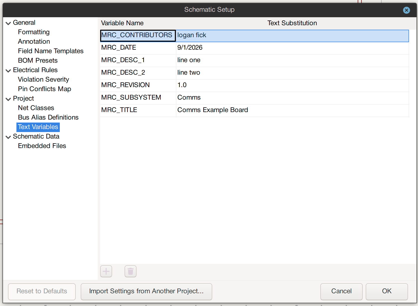
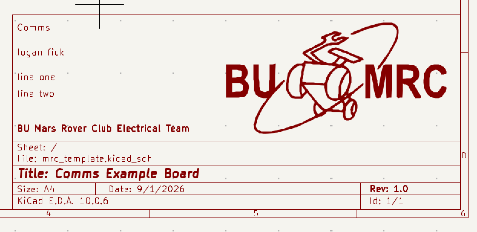
Click File -> Schematic Setup, then under Project -> Text Variables, populate all of the fields with the correct information such as contributors and board revision. Then click OK and you should see the bottom right of the schematic and layout correctly update. See a screenshots below:
| Qty | Value | Footprint | References |
|---|---|---|---|
| 1 | .22Ω | Resistor_THT:R_Axial_DIN0207_L6.3mm_D2.5mm_P10.16mm_Horizontal | RSC1 |
| 1 | 100+10+10Ω | Resistor_THT:R_Axial_DIN0207_L6.3mm_D2.5mm_P10.16mm_Horizontal | R1 |
| 1 | 100μf | Capacitor_THT:CP_Radial_D6.3mm_P2.50mm | C1 |
| 1 | 180Ω | Resistor_THT:R_Axial_DIN0207_L6.3mm_D2.5mm_P10.16mm_Horizontal | R8 |
| 1 | 1N5819 | Diode_THT:D_DO-41_SOD81_P10.16mm_Horizontal | <<D1 |
| 1 | 220 uH | Inductor_THT:L_Radial_D7.5mm_P5.00mm_Fastron_07P | L1 |
| 1 | 2200Ω | Resistor_THT:R_Axial_DIN0207_L6.3mm_D2.5mm_P10.16mm_Horizontal | R2 |
| 1 | 330μf | Diode_THT:D_DO-41_SOD81_P10.16mm_Horizontal | CO1 |
| 1 | 680pf | Capacitor_THT:C_Disc_D5.0mm_W2.5mm_P5.00mm | CT1 |
| 1 | MC34063AP | Package_DIP:DIP-8_W7.62mm | U1 |


fabianmink/MarbleAccelerator
An accelerator / coilgun for metallic marbles


cookiemonsternz/fallout-badge
A badge with holes for mounting to a lanyard, containing within a full miniature analogue synthesizer / sequencer.

It measures 50 × 70 mm and has 4 copper layers, 1.6 mm thick.
10 parts, built around the MC34063AP. The full list of its parts is on this page, with links to each part's symbol and footprint where PCBKit's library has them.
From the eric-greene1/BUMRCKiCad repository on GitHub, at the commit this page was made from: the board is kicad/EricOnboardingProject/EricOnboardingProject.kicad_pcb and its schematic kicad/EricOnboardingProject/EricOnboardingProject.kicad_sch. PCBKit opens the board in the browser, with nothing to install.
Its repository publishes it under the MIT licence: you may reuse it on that licence's terms (keep the author's notice, and for a copyleft licence share your changes alike).