
2 layers75 × 50 mm
Hiside switch
fabianmink/MarbleAccelerator
An accelerator / coilgun for metallic marbles
25 parts1BSD-2-Clause

 fabianmink/MarbleAccelerator1
An accelerator / coilgun for metallic marbles
Boost converter is an open-source printed circuit board by fabianmink, from the fabianmink/MarbleAccelerator repository on GitHub, published under the BSD-2-Clause licence. It is a 2-layer board of 75 × 40 mm with 30 parts on 13 nets, routed with 100 tracks and 0 vias.
It is built around the MC34063AP. Its parts include 12 resistors, 6 capacitors, 3 connectors, 1 IC and 1 diode. It belongs with the power boards of this library.
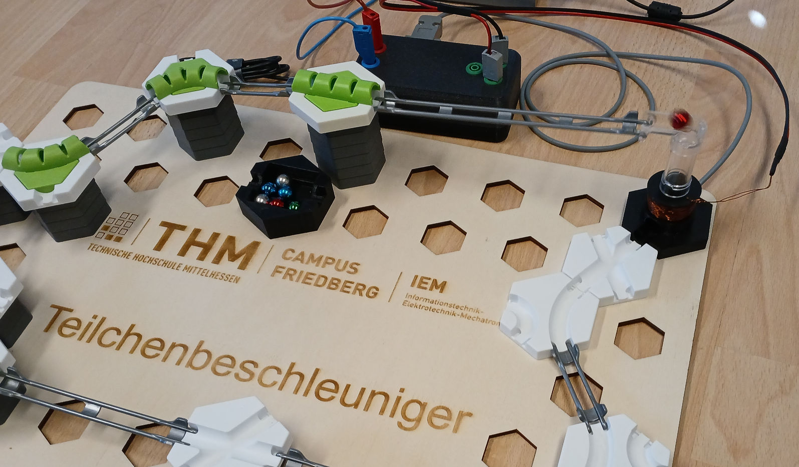
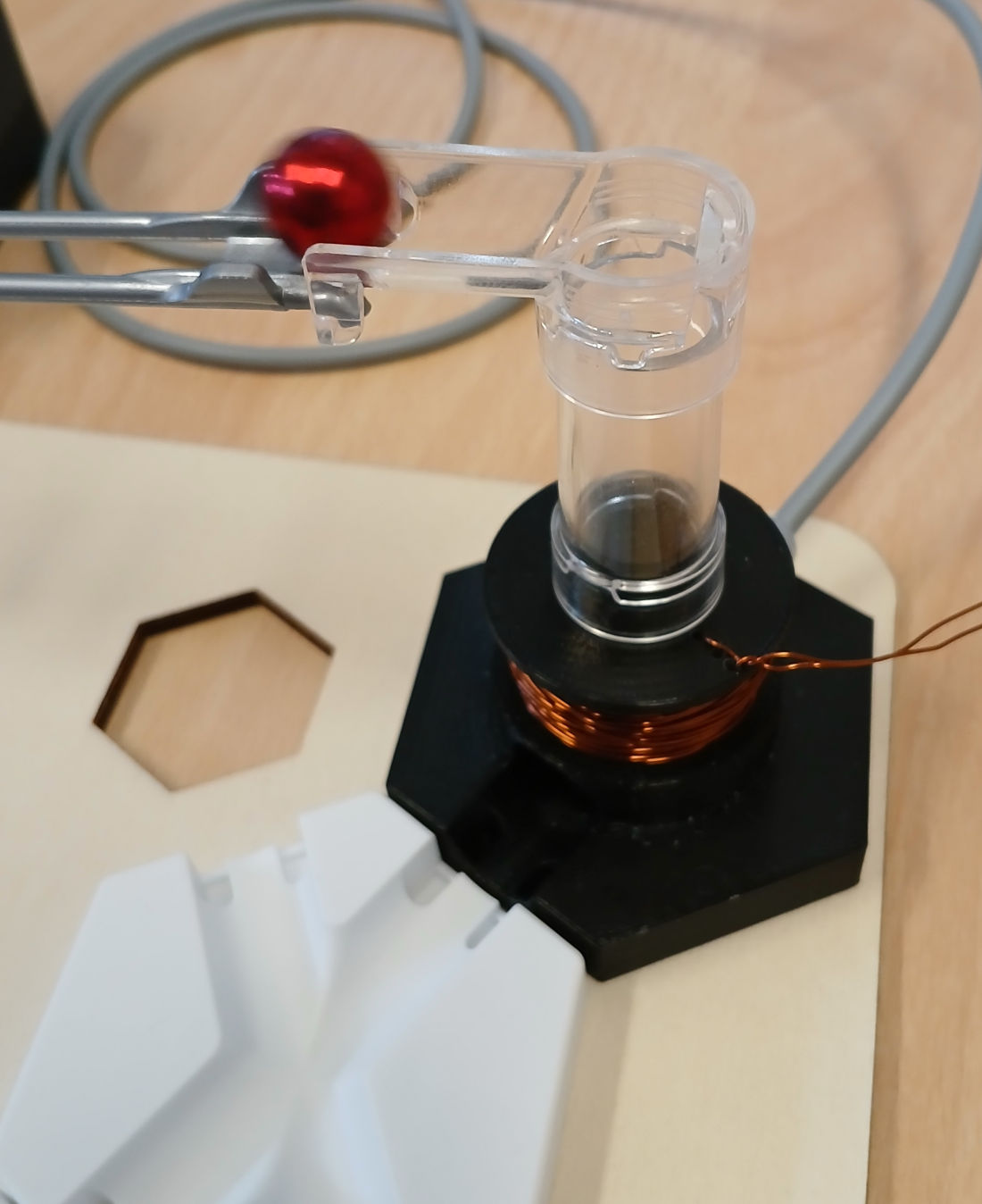
This project deals with the construction of various accelerators (coil guns) for metallic marbles. It might be used e.g. for the GraviTrax marble run (marble data: $m = 8.6 \mathrm{g}$, $d = 12.7 \mathrm{mm}$). It has been used in various student projects in electrical engineering bachelor's and master's programs in the IEM department at the THM Friedberg, e.g. this one
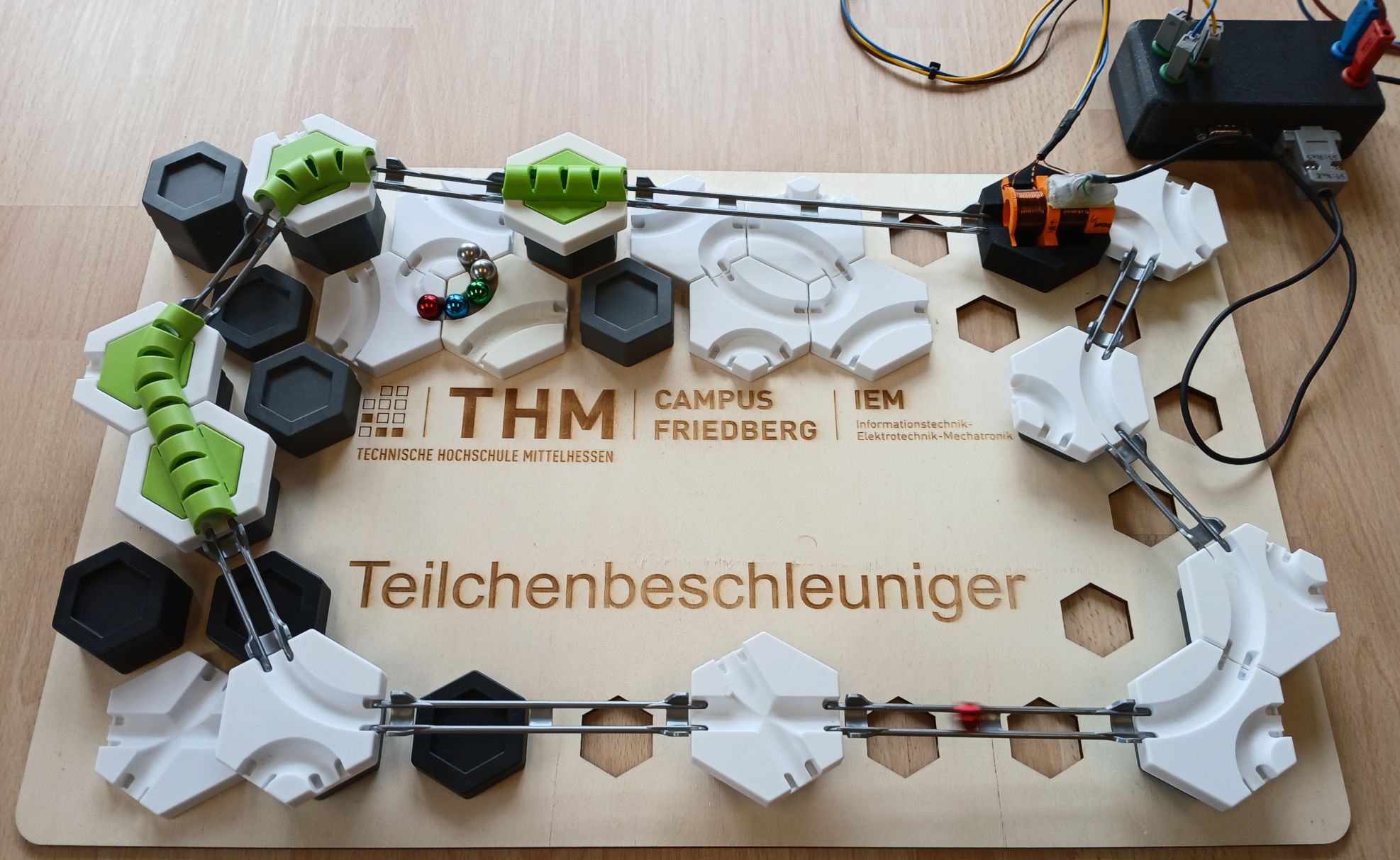
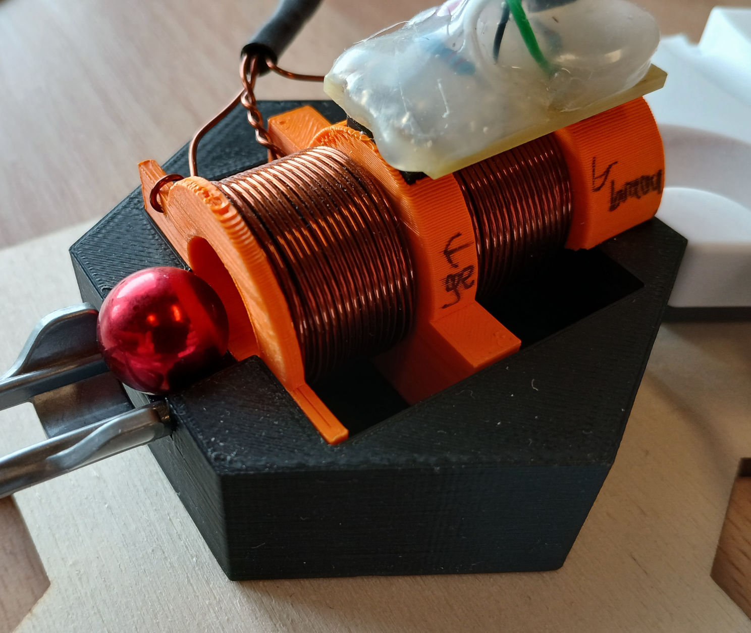
Coil winding cross sections are 15mm (coil length) x 7mm (inner radius 8mm, outer radius 15mm), leading to around 350 turns for 0.5mm wire diameter which results in an inductance of approximately 1mH.
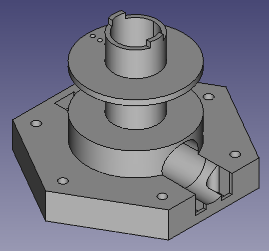
Horizontal CAD design (base and tube parts)
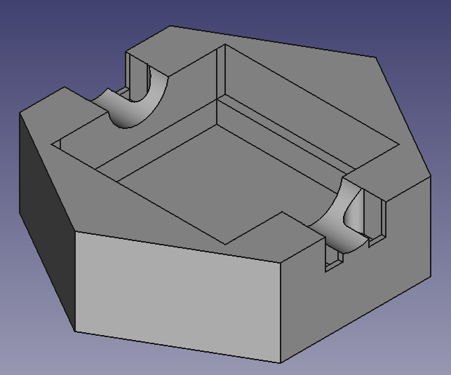
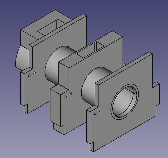
The design is intended to be used with EVERLIGHT ITR9904 optical sensor for marble detection.
Vertical CAD design (base part and output)
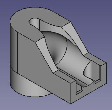
The design is intended to be used with Vishay CNY70 optical sensor for marble detection.
The advantage of the vertical design is that the marble is at a defined state (no movement, $v_\mathrm{z} = 0$) at the beginning. This makes the accelerator parameters easier to tune, as the current level and duration of the current pulse are always the same.
For an operating voltage of 24V, suitable wire diameters are in the range of 0.5mm ... 0.75mm.
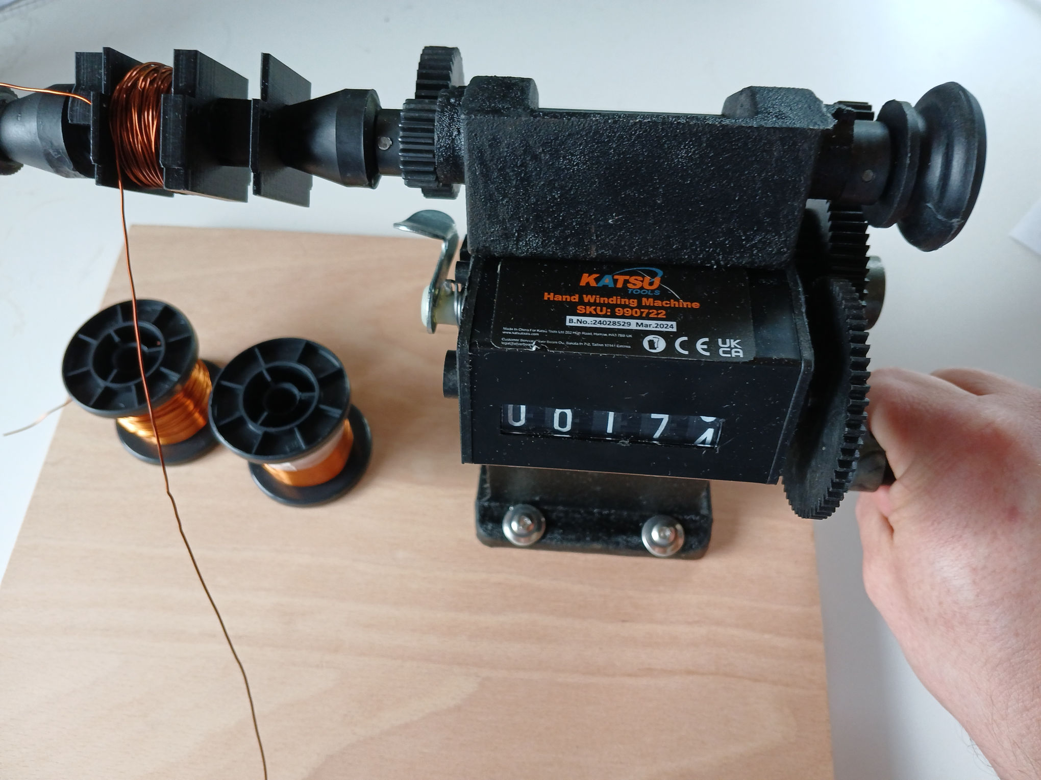
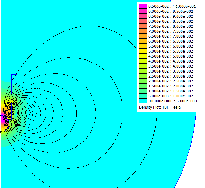
The fit is based on the following coenergy equation:
i.e.:
z-Direction Force: $F_\mathrm{z} = \frac{\partial E_{\mathrm{Co}}}{\partial z} = - \frac{1}{2} \cdot L_\mathrm{min} \cdot I^2 \cdot \left[ d \cdot \exp \left( -0.5 \cdot \left( \frac{z - z_0}{z_\mathrm{s}} \right)^2 \right) \right] \cdot \frac{z - z_0}{z^2_\mathrm{s}}$
Flux Linkage: $\Psi = \frac{\partial E_{\mathrm{Co}}}{\partial I} = L_\mathrm{min} \cdot I \cdot \left[ 1 + d \cdot \exp \left( -0.5 \cdot \left( \frac{z - z_0}{z_\mathrm{s}} \right)^2 \right) \right]$
Inductance: $L = \frac{\partial \Psi}{\partial I} = \frac{\partial^2 E_{\mathrm{Co}}}{\partial I^2} = L_\mathrm{min} \cdot \left[ 1 + d \cdot \exp \left( -0.5 \cdot \left( \frac{z - z_0}{z_\mathrm{s}} \right)^2 \right) \right]$
Flux derivative: $\frac{\partial \Psi}{\partial z} = \frac{\partial^2 E_{\mathrm{Co}}}{\partial I \partial z} = - L_\mathrm{min} \cdot I \cdot \left[ d \cdot \exp \left( -0.5 \cdot \left( \frac{z - z_0}{z_\mathrm{s}} \right)^2 \right) \right] \cdot \frac{z - z_0}{z^2_\mathrm{s}}$ (needed for induced voltage calculation)
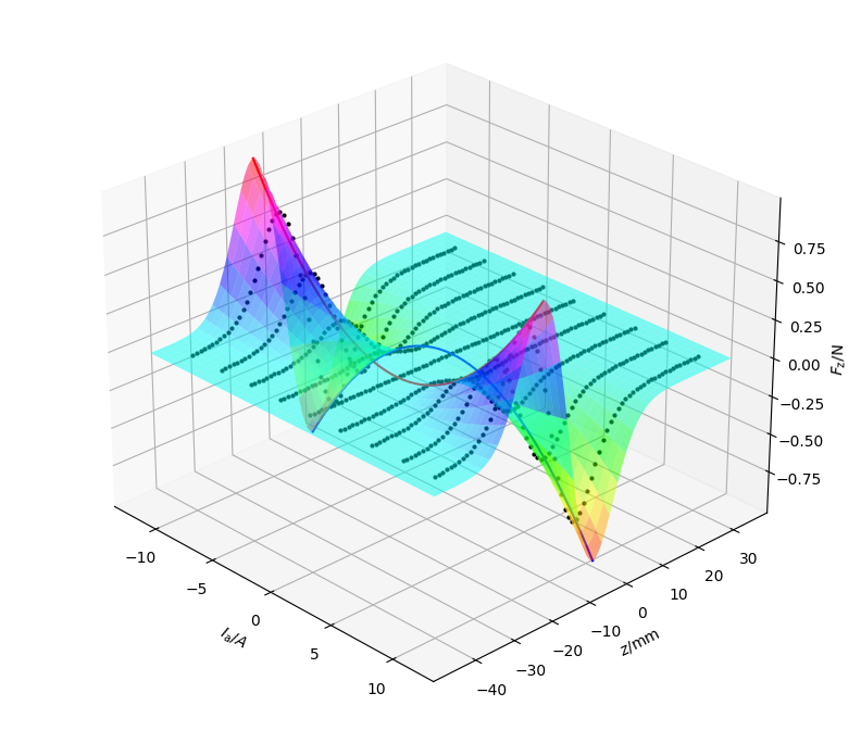
Maximum force for given current occurs at the inflection points of $E_{\mathrm{Co}}$, i.e. at $z = z_0 \pm z_\mathrm{s}$: $F_\mathrm{z,max} \left( I \right)= \frac{1}{2} \cdot L_\mathrm{min} \cdot I^2 \cdot d \cdot \exp \left( -0.5 \right) \cdot \frac{1}{z_\mathrm{s}}$
Resulting examplary fitted force:
The dynamic simulation implements the following equations:
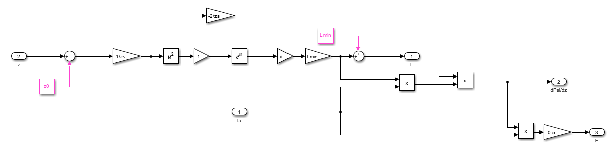
Model:
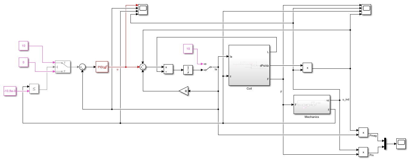
Coil electromagnetic subsystem:
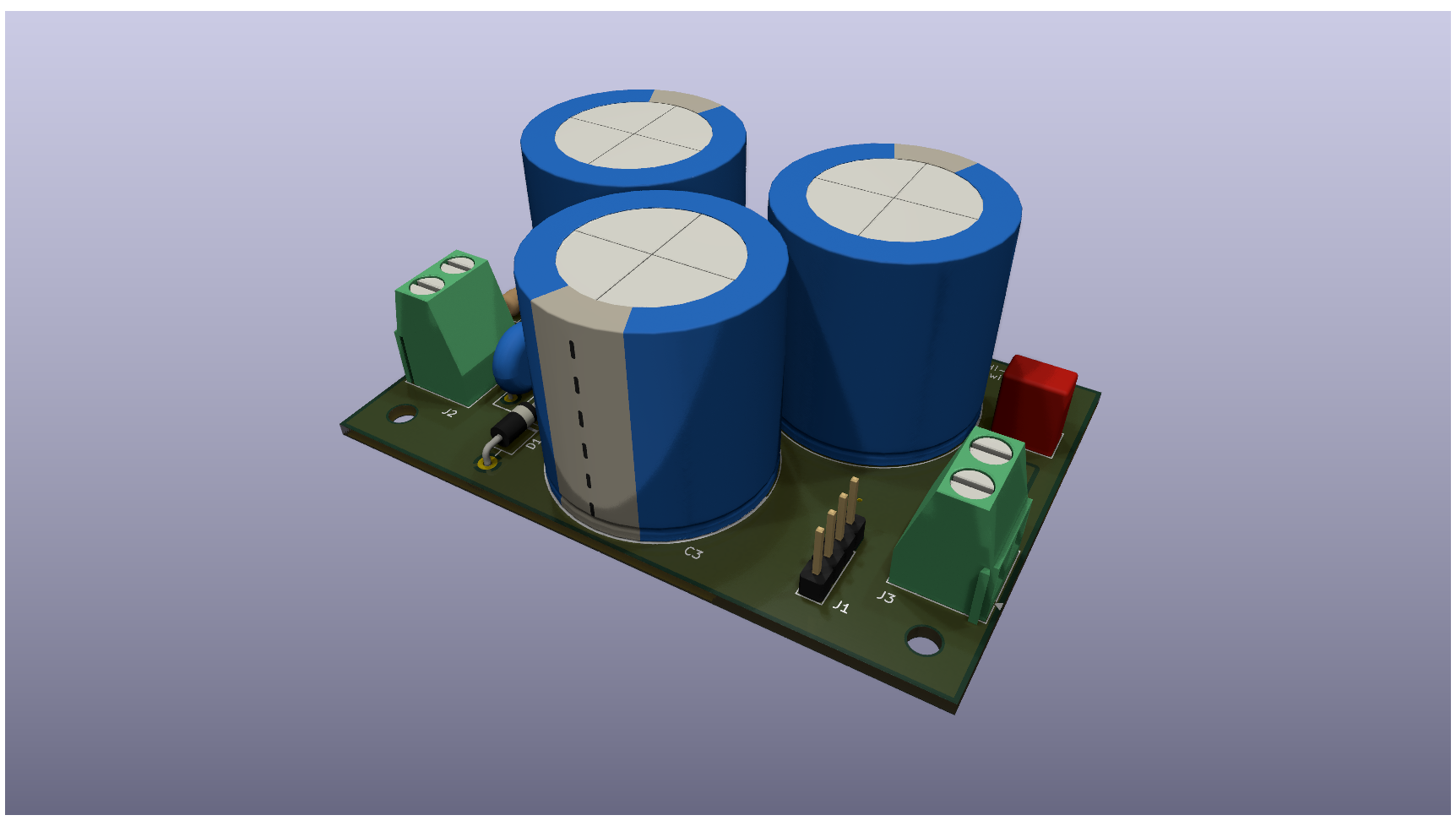
The software is designed for STM's B-G431B-ESC1 (Discovery kit with STM32G431CB MCU); it also includes the neccessary power MOSFETs. The supply voltage is 24V. An external capacitor of approximately 20mF is recommended in order to provide the high pulsed currents of 10..20A for durations of a few 10ms.
In case the coil should be battery-powered (e.g. from 3x AA alkaline cells / 4.5V), the boost converter board can be used.
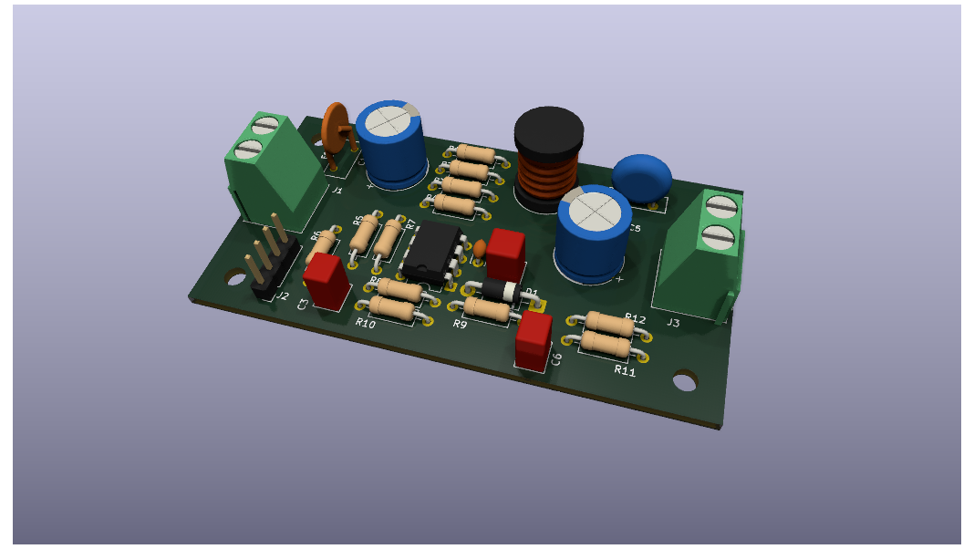
Can be used to power the coil.
| Qty | Value | Footprint | References |
|---|---|---|---|
| 12 | R | Resistor_THT:R_Axial_DIN0207_L6.3mm_D2.5mm_P10.16mm_Horizontal | R1, R2, R3, R4, R5, R6, R7, R8, R9, R10, R11, R12 |
| 4 | MountingHole | MountingHole:MountingHole_3.2mm_M3 | H1, H2, H3, H4 |
| 2 | C | Capacitor_THT:C_Rect_L4.6mm_W3.8mm_P2.50mm_MKS02_FKP02 | C3, C6 |
| 2 | Screw_Terminal_01x02 | TerminalBlock_Phoenix:TerminalBlock_Phoenix_MKDS-1,5-2-5.08_1x02_P5.08mm_Horizontal | J1, J3 |
| 1 | 1N5819 | Diode_THT:D_DO-41_SOD81_P10.16mm_Horizontal | D1 |
| 1 | C | Capacitor_THT:C_Disc_D3.0mm_W2.0mm_P2.50mm | C2 |
| 1 | C | Capacitor_THT:C_Rect_L4.6mm_W4.6mm_P2.50mm_MKS02_FKP02 | C4 |
| 1 | C_Polarized | Capacitor_THT:CP_Radial_D10.0mm_P2.50mm_P5.00mm | C1 |
| 1 | C_Polarized | Capacitor_THT:CP_Radial_D10.0mm_P5.00mm_P7.50mm | C5 |
| 1 | Conn_01x04_Pin | Connector_PinHeader_2.54mm:PinHeader_1x04_P2.54mm_Vertical | J2 |
| 1 | L | Inductor_THT:L_Radial_D10.0mm_P5.00mm_Fastron_07P | L1 |
| 1 | MC34063AP | Package_DIP:DIP-8_W7.62mm | U1 |
| 1 | Polyfuse | Fuse:Fuse_BelFuse_0ZRE0005FF_L8.3mm_W3.8mm | F1 |
| 1 | Thermistor_PTC | Varistor:RV_Disc_D9mm_W3.3mm_P5mm | TH1 |
fabianmink/MarbleAccelerator
An accelerator / coilgun for metallic marbles


cookiemonsternz/fallout-badge
A badge with holes for mounting to a lanyard, containing within a full miniature analogue synthesizer / sequencer.


dochoacruz/Proyecto-G2-EDP-R5053-2025
Proyecto de Electrónica de Potencia R5053-2025
It measures 75 × 40 mm and has 2 copper layers, 1.6 mm thick.
30 parts, built around the MC34063AP. The full list of its parts is on this page, with links to each part's symbol and footprint where PCBKit's library has them.
From the fabianmink/MarbleAccelerator repository on GitHub, at the commit this page was made from: the board is electronics/boost_converter/boost_converter.kicad_pcb and its schematic electronics/boost_converter/boost_converter.kicad_sch. PCBKit opens the board in the browser, with nothing to install.
Its repository publishes it under the BSD-2-Clause licence: you may reuse it on that licence's terms (keep the author's notice, and for a copyleft licence share your changes alike).