6 layers276 × 93.5 mm
Mnt reform motherboard
Junkz3/wrench-board
A senior microsoldering technician, available to every repair shop from the seasoned pro to the apprentice. Powered by Claude Opus 5
505 parts259

 erhancm/LogicPad
A programmable USB macro pad — and a desktop app that makes it yours. Assign macros, build lighting profiles, auto-switch layouts per app, back up your setups, and update firmware — all over USB.
3x3 board is an open-source printed circuit board by erhancm, from the erhancm/LogicPad repository on GitHub, published under the Apache-2.0 licence. It is a 2-layer board of 69.1 × 104.8 mm with 124 parts on 103 nets, routed with 1,243 tracks and 177 vias.
It is built around the TLV62568DBV and BSS84. Its parts include 61 resistors, 13 transistors, 11 capacitors, 10 diodes and 10 switches. It belongs with the STM32 boards of this library.


A programmable USB macro pad — and a desktop app that makes it yours.
Assign macros, build lighting profiles, auto-switch layouts per app, back up your setups, and update firmware — all over USB.




Configurator · Features · Hardware · Quick start · Download app
LogicPad shows up as a standard USB keyboard when you plug it in, so it works without any software. The Windows, macOS, and Linux configurator app (built with Tauri 2) gives you a full-screen key editor, YAML profile packs, automatic profile switching based on which app you're using, and firmware updates over USB.
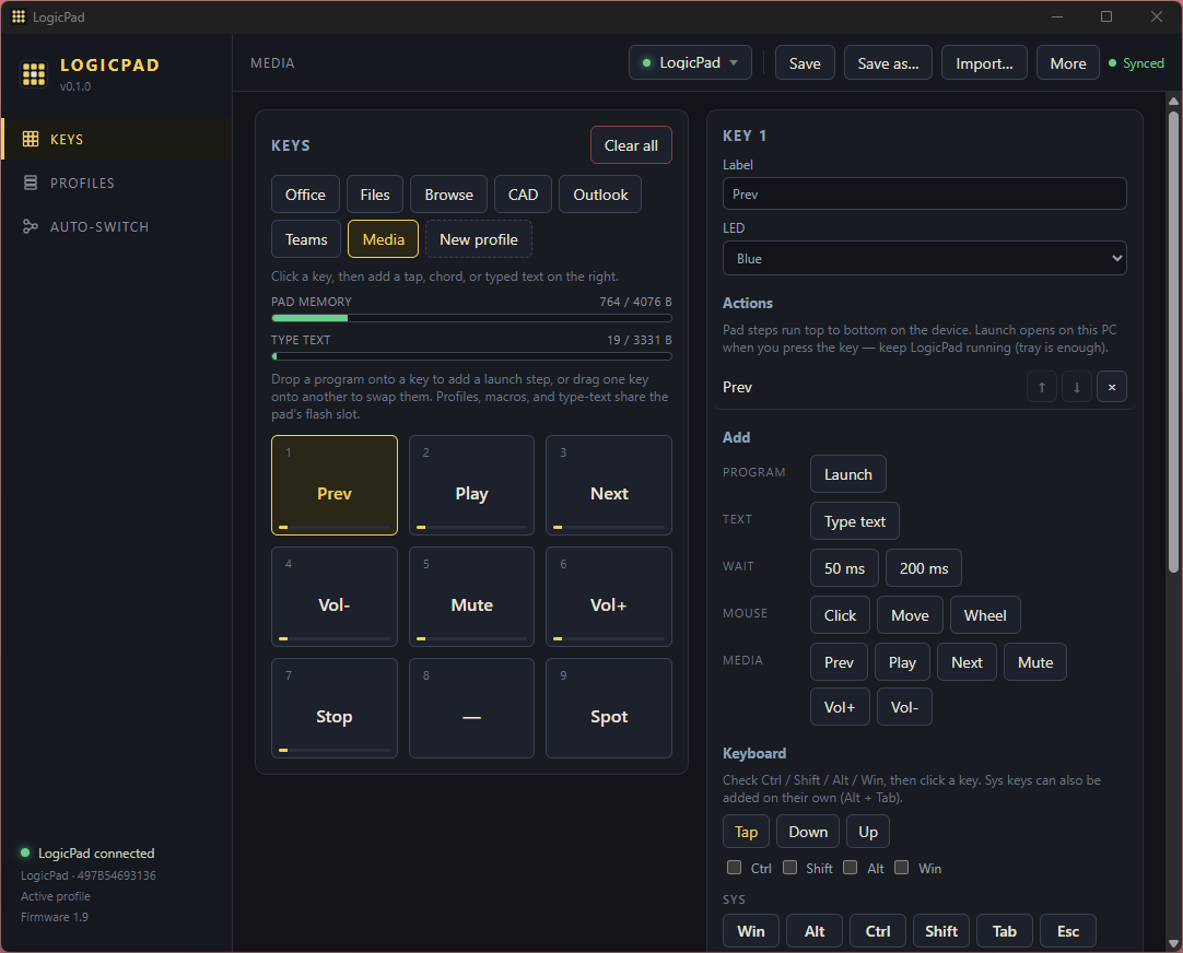
Keys — macros, chords, typed text, and drag-and-drop PC program launch | |
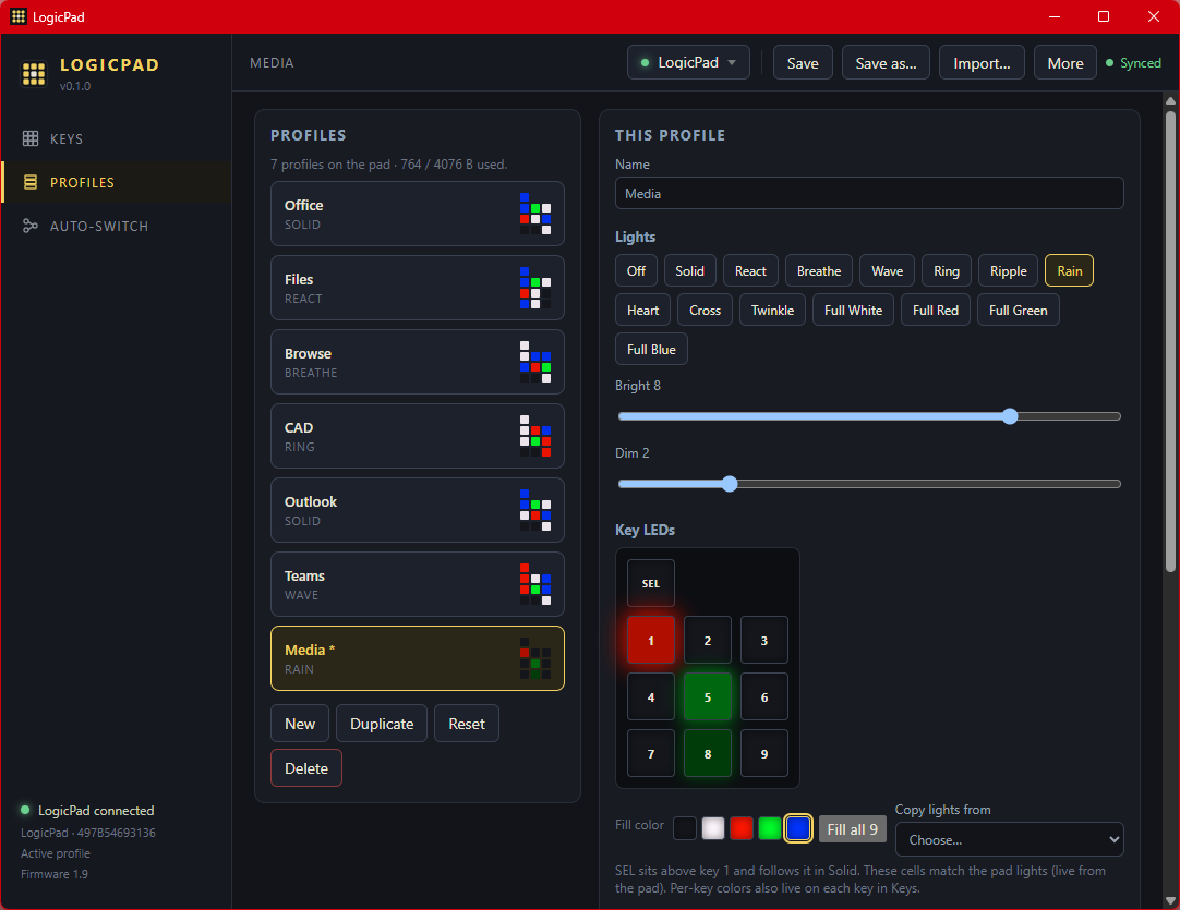
Profiles — wave, ripple, breathe & rain lighting · per-key colours · OLED settings |
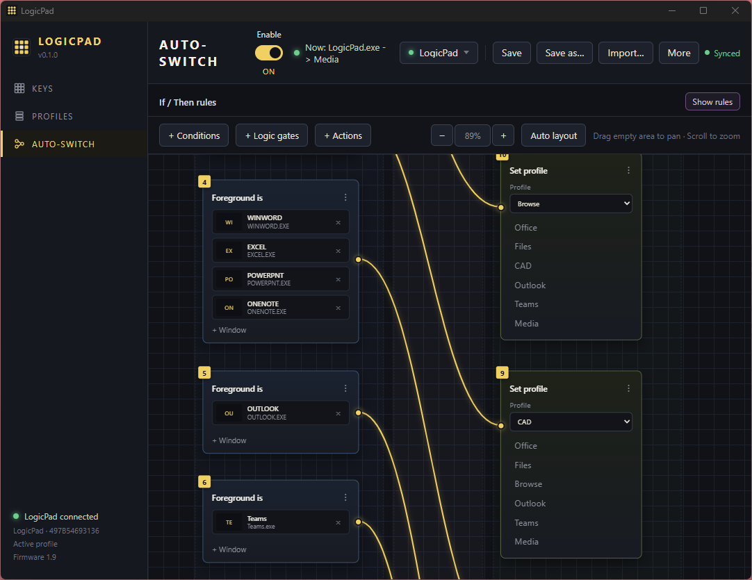
Auto-switch — switch profiles when you focus or run specific apps |
The app has a built-in simulated LogicPad so you can try everything without owning the physical board. Note that the software is still a work in progress — some features aren't implemented yet.
Download from Releases:
| Platform | Download | Install |
|---|---|---|
| Windows | LogicPad_*_x64-setup.exe | Run the installer |
| macOS | LogicPad_*_x64.dmg | Open the DMG, drag LogicPad to Applications |
| Linux | LogicPad_*_amd64.AppImage | chmod +x LogicPad_*.AppImage && ./LogicPad_*.AppImage |
| Linux | logicpad-app_*_amd64.deb | sudo apt install ./logicpad-app_*_amd64.deb |
| All | LogicPad-Productivity.yaml | Import in the app (Import…) Example configuration |
Linux note: You'll need to install a udev rule so the app has permission to communicate with the pad over USB. Without it, the app can't detect the device.
Build from source: cd "04 Software/logicpad-app" && npm install && npm run build:app
Showcase demo: 04 Software/logicpad-app/showcase/ comes with five pre-built profiles.
Full app docs: 04 Software/logicpad-app/README.md
| Keys | A 3×3 grid of macro keys. Each key can trigger a keyboard shortcut, mouse click, media control or typed string (up to 240 bytes per key). You can also launch a PC program directly from a key. |
| Profiles | Create as many profiles as the internal flash allows. Each profile has its own lighting mode (wave, ripple, breathe, rain) or per-key RGB colours. |
| Auto-switch | A visual node graph lets you define rules like "when Spotify is focused, switch to the Media profile." Supports foreground-app and running-app checks, AND/OR logic gates. |
| YAML packs | Export your entire setup — profiles, key mappings, and auto-switch rules — to a single YAML file. Import it later or share it with others. Use Save as… / Import… in the app. |
| On-board bootloader | Every board has a 4 KB USB HID bootloader. After the first flash, you can update firmware straight from the app — no ST-Link or disassembly needed. If something goes wrong, hold SEL while plugging in to enter recovery mode. |
| On-device OLED editor | Don't have the app? You can configure keys, profiles, and settings entirely from the pad's OLED screen using the selector and the nine keys as a d-pad. |
| Plug-and-play HID | LogicPad appears as a standard USB keyboard, mouse, and media device. No custom drivers needed on Windows, macOS, or Linux. |
| Open hardware | Full KiCad schematic and PCB layout. |
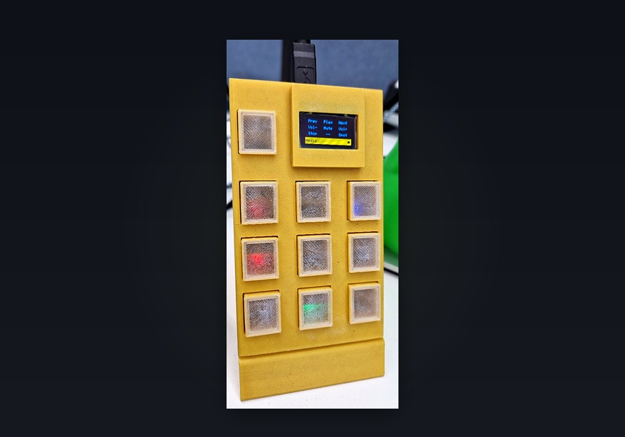
9 macro keys + selector · 0.96″ OLED · per-key RGB · STM32F103 · 3D-printable enclosure
| Spec | Detail |
|---|---|
| MCU | STM32F103C8 (ARM Cortex-M3) — 64 KB flash, 20 KB RAM |
| Keys | 9 macro keys + 1 selector button |
| Display | 0.96″ SSD1306 OLED, 128×64 pixels, connected over I²C |
| Lighting | Per-key RGB using 2020-size LEDs |
| USB | Composite HID device — keyboard + mouse + media controls + vendor-specific reports for app communication |
| Flash map | 4 KB bootloader · 52 KB application · 8 KB persistent config store |
Current hardware revision: V0.2 in 02 Electronics/V0.2/.
Every LogicPad board has a 4 KB USB HID bootloader baked into flash. Once the board has been programmed for the first time, all future firmware updates happen over a regular USB cable — no ST-Link, no SWD debugger, and no need to open the enclosure.
Updating firmware:
Release CMake preset in 03 Firmware/Firmware/.LogicPad.bin file. The app communicates with the bootloader over USB HID and flashes the new image.Recovery: If a firmware update fails or the app won't boot, hold the SEL button while plugging in the USB cable. This forces the board into bootloader mode so you can re-flash.
First-time programming still requires an ST-Link programmer (one-time only). The factory image LogicPad_factory.hex bundles both the bootloader and the application. See 03 Firmware/bootloader/README.md for details.
Plug in USB. The host OS recognises LogicPad as a standard HID keyboard (plus mouse and media controls if you've configured them). No drivers, no pairing — it just works.
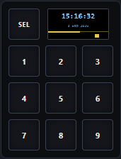
Navigate the OLED menus. A short press on the selector (SEL) button opens the on-device menu. Inside menus, the nine keys double as a d-pad for navigation:
Short press SEL = go back one level. |
|
Assign your macros. Factory boards ship with empty key slots. You can assign macros either from the OLED menu (no PC required) or from the app. The app has more options.
You'll need an ARM GCC toolchain and CMake. Both the bootloader and application firmware use CMake presets.
03 Firmware/bootloader/ and build with the Release CMake preset.03 Firmware/Firmware/ and build with the Release CMake preset.LogicPad_factory.hex and flash it via ST-Link (this is the only time you need ST-Link).LogicPad.bin. The on-board bootloader handles the rest over USB.The repo is organised by discipline, numbered so it sorts in a logical order:
| Path | Contents |
|---|---|
01 Documentation/ | Hardware and protocol docs — MCU pinout, HID report format, OLED menu structure, and C4 architecture diagrams. |
02 Electronics/V0.2/ | KiCad schematic and PCB layout for the current board revision, plus BOM and Gerber files for manufacturing. |
03 Firmware/Firmware/ | Production firmware for the STM32F103. CMake-based build with ARM GCC. Handles USB HID, key scanning, OLED display, RGB lighting, and config storage. |
03 Firmware/bootloader/ | On-board USB HID bootloader. Occupies the first 4 KB of flash and allows firmware updates over USB without a debugger. |
04 Software/logicpad-app/ | Desktop configurator app — Tauri 2 (Rust + web frontend). Handles key editing, profile management, auto-switch rules, YAML import/export, and firmware updates. |
05 Hardware/ | 3D-printable enclosure — STEP files for the case and button caps. |
.github/assets/ | Images used in this README. |
Contributions are welcome — whether it's a bug report, a feature request, or a pull request. If you're planning a larger change, it's worth opening an issue first to discuss the approach. By contributing, you agree that your contributions will be licensed under Apache 2.0.
| Issue | Type | Status | Notes |
|---|---|---|---|
| Sometimes you can't pan across the node editor when clicking on an empty area and dragging the mouse | Software | Open | Needs more investigation |
| OLED flicker or banding when taking pictures with camera | Software | Open | To do with refresh rate |
| Standby Clock setting is not persistant | Firmware | Open | When powering the unit off and on, the standby clock is reset to the default setting |
| Not all standby clock styles work | Software + Firmware | Open | Needs more investigation |
| LEDs can't reach full brightness in custom lighting modes | Hardware | Open | The LEDs are scanned one key at a time (1/9 duty cycle), so each LED is only actually on for a fraction of the time — the rest just looks lit because of persistence of vision. The STM32F103's GPIO pins can't source enough current to drive all 27 LEDs (9 keys × 3 colours) at once, so the per-LED brightness is capped by the scan rate. |
| Feature | Type | Status | Notes |
|---|---|---|---|
| Custom scripting assignable to each button | Software | Planned | Python/Lua scripts — TBD |
| Mouse and keyboard recording | Software | Planned | Record input sequences and replay them from a key |
| OCR-based automation | Software | Planned | Use image recognition to perform actions based on what's on screen |
| Long press functions | Software + Firmware | Planned | Different actions for short vs. long key presses |
| Profile hotkeys | Firmware | Planned | Assign a key to cycle through or jump to specific profiles instead of going through the on-board menu (temporarily override auto-switch condition) |
| Feature | Status | Notes |
|---|---|---|
| Upgrade MCU to STM32F4 or RP2040 | Planned | More flash and RAM for larger configs, scripting support, and faster USB |
| USB-C connector | Planned | Replace the current Micro-USB with USB-C for better durability and reversibility |
| Hot-swap key sockets | Planned | Swap switches without soldering |
| Per-key addressable LEDs (WS2812B) | Planned | Remove the 1/9 scanning limitation and allow full brightness on all keys simultaneously |
| Larger OLED display | Planned | Upgrade from 0.96″ to 1.3″ for more readable menus and more info on screen |
| Rotary encoder | Planned | Add a clickable rotary encoder for volume control, scrolling, or menu navigation |
| Slider potentiometer | Planned | Linear slider for volume, brightness, or other continuous control |
| External flash storage | Planned | Dedicated flash chip or SD card slot — TBD. Would allow storing more profiles, macros, and recorded scripts on-device |
| Temperature and humidity sensor | Planned | Environmental sensor for ambient readings displayed on the OLED or used in automation rules. Including support for logging |
This project is licensed under the Apache License 2.0.
The third-party libraries bundled in 03 Firmware/Firmware/Drivers/ — namely the STM32 HAL, CMSIS, and ST's USB device library — are not covered by this license. They remain under their respective upstream licenses from STMicroelectronics and ARM.
| Qty | Value | Footprint | References |
|---|---|---|---|
| 30 | 165 | Resistor_SMD:R_0603_1608Metric | R27, R28, R29, R32, R33, R34, R37, R38, R39, R42, R43, R44, R47, R48, R49, R52 +14 |
| 13 | 100 | Resistor_SMD:R_0603_1608Metric | R1, R3, R5, R26, R31, R36, R41, R46, R51, R56, R61, R66, R71 |
| 13 | 47k | Resistor_SMD:R_0603_1608Metric | R2, R4, R6, R25, R30, R35, R40, R45, R50, R55, R60, R65, R70 |
| 11 | TestPoint_Probe | TestPoint:TestPoint_Pad_D1.5mm | TP1, TP2, TP3, TP4, TP5, TP6, TP7, TP8, TP9, TP10, TP11 |
| 10 | BSS84 | Package_TO_SOT_SMD:SOT-23 | Q4, Q5, Q6, Q7, Q8, Q9, Q10, Q11, Q12, Q13 |
| 10 | RGB_LED | HotKeyBoard:2020_RGB | D1, D2, D3, D4, D5, D6, D7, D8, D9, D10 |
| 10 | SW_Push | HotKeyBoard:gateronSwitch | SW1, SW2, SW3, SW4, SW5, SW6, SW7, SW8, SW9, SW10 |
| 7 | 100n | Capacitor_SMD:C_0603_1608Metric | C3, C4, C5, C6, C7, C8, C9 |
| 3 | 2N7002 | Package_TO_SOT_SMD:SOT-23 | Q1, Q2, Q3 |
| 2 | 12pF | Capacitor_SMD:C_0603_1608Metric | C1, C2 |
| 2 | 22 | Resistor_SMD:R_0603_1608Metric | R20, R21 |
| 2 | Conn_01x04 | Connector_PinHeader_2.54mm:PinHeader_1x04_P2.54mm_Vertical | J1, J3 |
| 1 | 100K | Resistor_SMD:R_0603_1608Metric | R8 |
| 1 | 10K | Resistor_SMD:R_0603_1608Metric | R22 |
| 1 | 1uH | HotKeyBoard:SRN3012TA-1R0Y | L1 |
| 1 | 22uF | Capacitor_SMD:C_0805_2012Metric | C11 |
| 1 | 4.7uF | Capacitor_SMD:C_1206_3216Metric | C10 |
| 1 | 453K | Resistor_SMD:R_0603_1608Metric | R7 |
| 1 | 8Mhz | Crystal:Crystal_SMD_5032-2Pin_5.0x3.2mm | Y1 |
| 1 | Fuse | Fuse:Fuse_1206_3216Metric | F1 |
| 1 | STM32F103C8Tx | Package_QFP:LQFP-48_7x7mm_P0.5mm | U1 |
| 1 | TLV62568DBV | Package_TO_SOT_SMD:SOT-23-5 | U2 |
| 1 | USB_B | Connector_USB:USB_B_OST_USB-B1HSxx_Horizontal | J2 |
It measures 69.1 × 104.8 mm and has 2 copper layers, 1.6 mm thick.
124 parts, built around the TLV62568DBV and BSS84. The full list of its parts is on this page, with links to each part's symbol and footprint where PCBKit's library has them.
From the erhancm/LogicPad repository on GitHub, at the commit this page was made from: the board is 02 Electronics/V0.2/3x3_board.kicad_pcb and its schematic 02 Electronics/V0.2/3x3_board.kicad_sch. PCBKit opens the board in the browser, with nothing to install.
Its repository publishes it under the Apache-2.0 licence: you may reuse it on that licence's terms (keep the author's notice, and for a copyleft licence share your changes alike).
Junkz3/wrench-board
A senior microsoldering technician, available to every repair shop from the seasoned pro to the apprentice. Powered by Claude Opus 5

mattvenn/basic-ecp5-pcb
Reference design for Lattice ECP5 FPGA. Featuring Raspberry Pi interface and 6 PMODs


Asbjoern/Kamstrup-Radius-Interface
ESP8266 interface for Kamstrup (Radius provided) electricity meter

Misaka0x2730/MioLink
ARM JTAG/SWD debugger (BlackMagic port) based on RP2040.


esden/glasgow-addons
Various interface addon boards and expansions for the Glasgow Digital Interface Explorer
