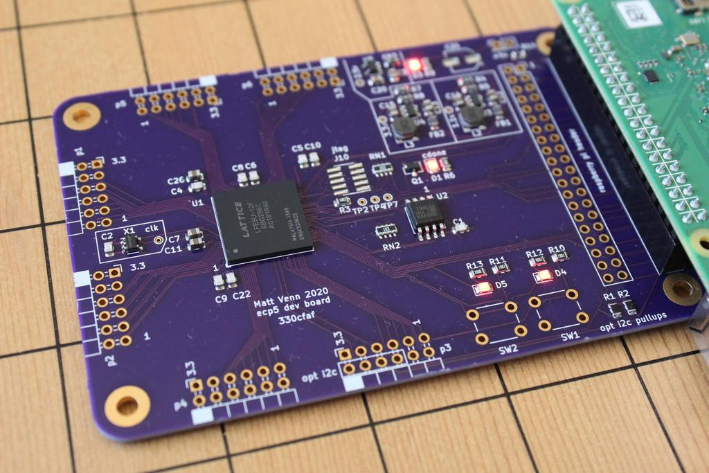
Basic ecp5-pcb
Reference design for Lattice ECP5 FPGA. Featuring Raspberry Pi interface and 6 PMODs
- Size
- 100 × 68 mm
- Copper layers
- 4
- Thickness
- 1.6 mm
- Parts
- 75
- Nets
- 241
- Pads
- 568
- Tracks, vias
- 1,148, 130
- Pours
- 2
- Routed
- Yes
- KiCad
- KiCad 5 (file 20171130)
- Created
- 16 Jul 2020
- Updated
- 17 Jul 2021
Overview
Basic ecp5-pcb is an open-source printed circuit board by mattvenn, from the mattvenn/basic-ecp5-pcb repository on GitHub, published under the CC0-1.0 licence. It is a 4-layer board of 100 × 68 mm with 75 parts on 241 nets, routed with 1,148 tracks and 130 vias.
It is built around the TLV62568DBV, IS25LP016D-JBLE and TLV73325PDBV. Its parts include 19 capacitors, 13 resistors, 10 connectors, 5 ICs and 4 diodes. It belongs with the fPGA and programmable logic boards and the FPGA and CPLD boards of this library.
Main components
3TLV62568DBV
SOT-23-5-40℃~+125℃@(TJ) 1 1.5MHz 1A 2.5V~5.5V 35uA 600mV~5.5V Adjustable Buck Buck Built-in Yes SOT-23-5 DC-DC Converters ROHSTexas InstrumentsDC-DC ConvertersIS25LP016D-JBLE
SOIC-8-208mil100,000 cycles 133MHz 16Mbit 2.3V~3.6V 20 Years 200us 5uA Power-on reset、Hardware write protection、Software write protection、Write enable latch SPI SOIC-8-208mil NOR FLASH ROHSISSINOR FLASHTLV73325PDBV
SOT-23-5-40℃~+125℃@(Tj) 1 120uVrms 2.5V 270mV@(300mA) 300mA 34uA 5.5V 68dB@(100Hz) Fixed Positive Under Voltage Lockout、Over Current Protection、Over Temperature Protection、Enable SOT-23-5 Voltage Regulators - Linear, Low Drop Out (LDO) Regulators ROHSTexas InstrumentsVoltage Regulators - Linear, Low Drop Out (LDO) Regulators
README
README.mdECP5 FPGA dev board
- Make an ECP5 FPGA dev board
- Keep it super simple and cheap
- Configured by on-board FLASH or direct with a Raspberry Pi
- 6 PMODs, 2 buttons, 2 LEDs, FLASH for configuration bitstreams.
- buttons are active low, LEDs are active low.
There is also an iCE40 version of this board: https://github.com/mattvenn/first-fpga-pcb
What a Lattice ecp5 FPGA needs
Check ECP5 family datasheet for more information.
- A clock input. Has to be provided by an oscillator, it doesn't have a crystal driver. Has to go to a PCLK pad
- 1.1v core supply for the internal logic. Should supply at least 600mA
- 2.5v auxiliary power supply. Should supply 10mA
- 3.3v IO supply for the IO pins. In this design, all banks of IO have the same supply. Same PSU is used for all PMODs, and is rated at 1A.
- Get configured over SPI interface. This can be done directly by a microcontroller or a computer, or the bitstream can be programmed into some FLASH, and the FPGA will read it at boot. If FLASH isn't provided then the bitstream needs to be programmed at every power up or configuration reset. See sysconfig documentation for more info.
- Decoupling capacitors for each IO bank.
PCB

-
4 layer board stackup: signal, gnd, 3.3v, signal
BOM
- FPGA ecp5 12k (LFE5U-12F-6BG256C) or 45k (LFE5U-45F-6BG256C) part, 14mm bga with 256 pins, 0.8mm pitch
- 2 x TLV62568 DC/DC switchers for core (1.1v) and IO (3.3v).
- 2.5v reg TLV73325PDBVT
- 16MHz oscillator SIT2001BI-S2-33N-16.000000G
- 16MB FLASH W25Q128JVSIM (same as icebreaker)
Design Review
- core supply (1.1v) is now DC/DC for 1A using TLV62568
- pmod and IO supply is now DC/DC for 1A using TLV62568
- move ferrite beads to input side of psu
- pullups on io2/3 of flash
- pulldown on tclk of jtag
- fix vias under bga by moving to 0.25mm drill 0.45mm annular ring
- add more ground vias under BGA
Errata
- Add missing qspi to the Pi to be able to program bitstream faster.
- configuration bits for FPGA should be tied to gnd not through a 10k resistor. The voltage is about 1v, so might be a little close to the threshold of the 3.3v IOBANK supply. Replace with 0Ohm resistors? Or just tie to gnd?
- used IS25LP016D-JBLE as flash, but it has problems with enabling QE for QSPI. Relace with the model used on icebreaker
- ecp5 SPI clock pin can't be used as an input, so have to add a bodge wire for SPI peripheral comms with Pi. See the test-spi-clk-in branch for a workaround.
RPi connection info
See test/mv_ecp.lpf for FPGA pinning. The following are the physical pins on the raspberry pi:
- serial: TX, RX on pins 8 and 10
- I2C: bitbanged on pins 38 and 40. Optional pullup resistors R1 & R2. Need to set up in boot/config.txt
- GPIOs: pins 31, 32, 33, 36.
- SPI: SDO, SDI, CLK, CE0 on pins 19, 21, 23, 24. These are connected to the onboard FLASH for bitstream config.
- Extra SPI CE1: pin 26
RPi Gotchas
- fomu_flash will leave the SPI device in an unusable state. Run
sudo rmmod spi_bcm2835 && sudo modprobe spi_bcm2835to reset it. - connected I2C pins are just GPIOs. I have found the Pi's I2C hardware unusable, so always use the slower bitbanged version.
To enable add this to /boot/config.txt:
dtoverlay=i2c-gpio,i2c_gpio_sda=21,i2c_gpio_scl=20,i2c_gpio_delay_us=8,bus=3
Test:
Simple test connects buttons to LEDs and toggles all other pins every second.
Yosys and NextPNR are used to create the bitstream and then it's copied to the Raspberry Pi specified by PI_ADDR in the Makefile.
Fomu-Flash is used to flash the SPI memory. Clone the repo on the Pi and set the path in the Makefile with FOMU_FLASH.
Run make in ./test to build, copy and program the bitstream.
PicoRV32 PicoSoC
I have adapted Claire Wolf's PicoRV32 Picosoc for this board: https://github.com/mattvenn/picorv32/tree/ecp5/picosoc
Reference
- http://www.latticesemi.com/ecp5
- In particular, the ECP5 and ECP5-5G Hardware Checklist is very useful
Inspiration
- https://github.com/Spritetm/hadbadge2019_pcb
- https://github.com/gregdavill/OrangeCrab
- https://www.crowdsupply.com/radiona/ulx3s
Attribution
- ECP5 library part for Kicad created with https://github.com/xesscorp/KiCad-Schematic-Symbol-Libraries
License
- Hardware is licensed under the Permissive CERN open hardware license v2
- Software is licensed under the GNU Lesser General Public License v2.1
- Documentation is licensed under the CCO
Open Source Hardware
This board is an OSHWA approved design: ES000012
Parts
75| Qty | Value | Footprint | References |
|---|---|---|---|
| 9 | 100n | Capacitor_SMD:C_0805_2012Metric | C1, C2, C4, C5, C6, C8, C9, C10, C22 |
| 6 | Conn_02x06_Odd_Even | Connector_PinSocket_2.54mm:PinSocket_2x06_P2.54mm_Horizontal | J3, J4, J5, J6, J7, J8 |
| 5 | 10k | Resistor_SMD:R_0805_2012Metric | R1, R2, R3, R10, R11 |
| 4 | 10u | Capacitor_SMD:C_0805_2012Metric | C7, C11, C15, C26 |
| 4 | 200R | Resistor_SMD:R_0805_2012Metric | R6, R9, R12, R13 |
| 4 | LED | LED_SMD:LED_0805_2012Metric | D1, D3, D4, D5 |
| 4 | MountingHole_Pad | MountingHole:MountingHole_3.2mm_M3_Pad | H1, H2, H3, H4 |
| 3 | Ferrite_Bead_Small | Inductor_SMD:L_0805_2012Metric | FB1, FB2, FB3 |
| 3 | TestPoint | TestPoint:TestPoint_THTPad_D1.0mm_Drill0.5mm | TP2, TP4, TP7 |
| 2 | 10k | Resistor_SMD:R_Array_Concave_4x0603 | RN1, RN2 |
| 2 | 1u | Capacitor_SMD:C_0805_2012Metric | C3, C20 |
| 2 | 2.2uH | Inductor_SMD:L_Taiyo-Yuden_NR-40xx | L2, L3 |
| 2 | 4.7u | Capacitor_SMD:C_0805_2012Metric | C12, C13 |
| 2 | Conn_02x20_Odd_Even | Connector_PinSocket_2.54mm:PinSocket_2x20_P2.54mm_Vertical | J2, J9 |
| 2 | LOGO | libs:oshw-logo-small | G***, G*** |
| 2 | SW_Push | Button_Switch_THT:SW_PUSH_6mm | SW1, SW2 |
| 2 | TLV62568DBV | Package_TO_SOT_SMD:SOT-23-5 | U3, U4 |
| 1 | 1.1v | TestPoint:TestPoint_THTPad_D1.0mm_Drill0.5mm | TP6 |
| 1 | 100k | Resistor_SMD:R_0805_2012Metric | R4 |
| 1 | 120k | Resistor_SMD:R_0805_2012Metric | R5 |
| 1 | 15k | Resistor_SMD:R_0805_2012Metric | R8 |
| 1 | 2.5v | TestPoint:TestPoint_THTPad_D1.0mm_Drill0.5mm | TP3 |
| 1 | 22u | Capacitor_SMD:C_0805_2012Metric | C14 |
| 1 | 3.3v | TestPoint:TestPoint_THTPad_D1.0mm_Drill0.5mm | TP1 |
| 1 | 68k | Resistor_SMD:R_0805_2012Metric | R7 |
| 1 | CP | Capacitor_SMD:CP_Elec_5x5.4 | C21 |
| 1 | Conn_01x02 | Connector_PinHeader_2.54mm:PinHeader_2x01_P2.54mm_Vertical | J1 |
| 1 | Conn_02x05_Odd_Even | Connector_PinHeader_1.27mm:PinHeader_2x05_P1.27mm_Vertical_SMD | J10 |
| 1 | ECP5U_45_CABGA256 | Package_BGA:BGA-256_14.0x14.0mm_Layout16x16_P0.8mm_Ball0.45mm_Pad0.32mm_NSMD | U1 |
| 1 | IS25LP016D-JBLE | Package_SO:SOIC-8_5.23x5.23mm_P1.27mm | U2 |
| 1 | Q_NMOS_GSD | Package_TO_SOT_SMD:SOT-23 | Q1 |
| 1 | SiT2001B | Package_TO_SOT_SMD:SOT-23-5 | X1 |
| 1 | TLV73325PDBV | Package_TO_SOT_SMD:SOT-23-5 | U5 |
| 1 | clock | TestPoint:TestPoint_THTPad_D1.0mm_Drill0.5mm | TP5 |
Questions
How big is the Basic ecp5-pcb PCB?
It measures 100 × 68 mm and has 4 copper layers, 1.6 mm thick.
What parts does the Basic ecp5-pcb use?
75 parts, built around the TLV62568DBV, IS25LP016D-JBLE and TLV73325PDBV. The full list of its parts is on this page, with links to each part's symbol and footprint where PCBKit's library has them.
Where can I download the Basic ecp5-pcb KiCad files?
From the mattvenn/basic-ecp5-pcb repository on GitHub, at the commit this page was made from: the board is hardware/basic-ecp5-pcb.kicad_pcb. PCBKit opens the board in the browser, with nothing to install.
Can I use the Basic ecp5-pcb design in my own project?
Its repository publishes it under the CC0-1.0 licence: you may reuse it on that licence's terms (keep the author's notice, and for a copyleft licence share your changes alike).
Similar boards
- 4 layers101.8 × 83 mm
- 6 layers50.5 × 66.4 mm

- 2 layers100 × 68 mm

- 2 layers103.9 × 43.5 mm

- 2 layers118.2 × 73 mm

- 2 layers35.6 × 18.8 mm

Samd51 micropython 9
gnilsson2/YAPP_Box_KiCad_Generator
Generate Openscad boxes from KiCad PCB files.
22 partsMIT - 4 layers100 × 100 mm

RPI RP2040-MINIMAL R3-S1
thegamer3-141/16bit_transistor_computer
A 16-bit computer built from discrete transistors, inspired by Ben Eater's famous 8-bit breadboard computer project.
81 parts - 4 layers165 × 107 mm