2 layers245 × 60 mm
Black devil
Synthron/SymAsym
High Power Audio Amplifier based on the Red Devil SymAsym PCBs from audiopcb.de
124 parts2

 ereisch/Data_East_PS
Data East pinball power supply board, replacement for 520-5047-02
Power Supply is an open-source printed circuit board by ereisch, from the ereisch/Data_East_PS repository on GitHub, published under the GPL-3.0 licence. It is a 2-layer board of 254 × 187.3 mm with 114 parts on 83 nets, routed with 889 tracks and 83 vias.
It is built around the LM3150MH, LM2991T and IRLZ34N, with the MJE15030, 20TQC100MYF and 6TPE150M among its other parts. Its parts include 28 capacitors, 28 resistors, 12 diodes, 10 connectors and 7 fuses. It belongs with the power boards of this library.


Data East pinball power supply board, replacement for 520-5047-02
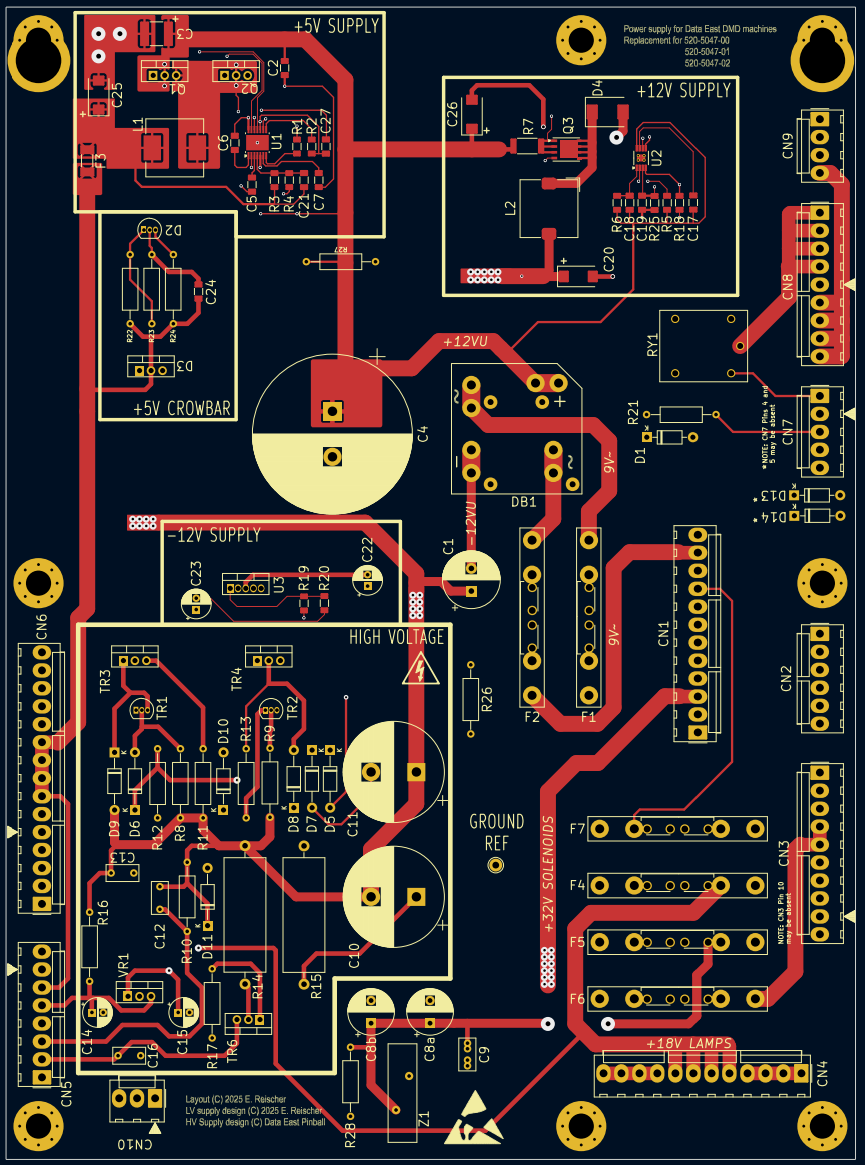
A short while ago, I became frustrated with the replacement power supply options available for Data East pinball machines. The factory original ones had several key deficiencies as I saw them:
Additionally, I didn't like many aftermarket supplies:
So, I set out to build my own, open-source, higher-efficiency version. Since many older machines are transitioning to LED displays, the high-voltage section is a part-for-part copy from the original schematic (I'm using TFTC's schematics, as they're the highest resolution I could find on IPDB). The 5V, +/-12V, and GI control sections are redesigns for efficiency, simplicity, or serviceability, and will be adding crowbar circuits to each for protection from HV display faults. Once complete, I will post Gerbers and a BOM shopping cart to do a complete build. Using kicad version 8.0.8.
Gathering all my research into this section.
+5V output on the stock supply is limited to 5.5A. This was ascertained from the MC1723 datasheet, which specifies the limiting current via the Rsense (R6) resistor value, which is 0.12 ohms in the -02 version. The equation is: Isc = 0.66 / Rsense
Power limits of the HV section isn't as clear from the components (all are well oversized), but is limited to a combined ~45W between the 90 and 100V legs of the input transformer, due to fuse F7. Also, the voltage tolerances on this section aren't as stringent as the delta-V between them, since they aren't driving logic, but a VFD. As long as the high end of the voltages don't exceed the HV shift registers, any damage done will be long-term damage to the vacuum display itself.
The +/- 12V rails are going to be regulated; the -12V is only used in the sound board, and even there it's further regulated to -5V for op-amps. The +12V rail is used for sound (which should be cleaner than it is from factory), and some accessories that vary by game (e.g., motors, widgets, etc.). As it sits from the factory, these rails can have as much as 1-2V of ripple, which is bad for the sound board. However, if you examine the sound card schematic, the only place the +12V is used is to power the MB3730 drivers, but since these are advertised to support 8-16V of supply, we can drive this with ~10V of clean power rather than 12V of noisy power. So to keep things simple, we'll split the +12V rail up into two supplies: one with active regulation that drives CN6, and one that's just rectified and filtered that'll go everywhere else. Using round numbers, assume the regulated +12V will need on the order of 50W of power. The -12V rail will be active regulated, but the 7905 on the sound board only needs -7V or greater(?), so we'll make this rail actually -10V to simplify the regulator design to just buck rather than buck-boost.
Glass fuses will be replaced with blade-style automotive fuses, which are both cheaper and easier to change. An added bonus is that the connectors for those is more robust too. Will leave F7 for the HV section as the glass fuse though since blade fuses aren't rated for that voltage.
Note: all of this was analyzed using the 10-5003-00 in my Jurassic Park system.
Power limits of the transformer: Unfortunately, these are undocumented from what I've been able to find. However, we can infer minimum limits from the factory fusing specifications on the various systems that utilized it:
| Pair Colors | Inductance | Q-Factor | Resistance | Tap Ratio (Re: Black/Brown) |
|---|---|---|---|---|
| Black / Brown | 15.107 mH | 11.00 | 8.628 Ω | -- |
| Black / Orange | 18.673 mH | 10.57 | 11.079 Ω | |
| White-Black / White-Brown | 15.159 mH | 10.75 | 8.840 Ω | 1:1 |
| White-Black / White-Orange | 18.636 mH | 10.64 | 11.025 Ω |
| Pair Colors | Inductance | Tap Ratio (Re: Black/Brown) | Q-Factor | Resistance | Voltage (AC) | Power Delivery (min) | Usage |
|---|---|---|---|---|---|---|---|
| Yellow-White / Yellow | 55.7 μH | 16.59:1 | 5.6 | 0.060 Ω | 6V | 120W | General Illumination |
| Grey-White / Grey | 138.9 μH | 10.42:1 | 8.42 | 0.103 Ω | 9V | 63W | Logic, Sound & Motors |
| Grey-White / Grey-Green | 139.3 μH | 10.42:1 | 8.79 | 0.099 Ω | 9V | 63W | Logic, Sound & Motors |
| Grey-Green / Grey | 558.3 μH | 11.78 | 0.299 Ω | ||||
| Blue-White | 277.9 μH | 7.60:1 | 9.02 | 0.194 Ω | 13V | 104W | Lamps |
| White-Red | 1148.2 μH | 3.60:1 | 12.05 | 0.595 Ω | 25V | 200W | Solenoids |
| Black-Yellow | 3.908 mH | 1.97:1 | 11.89 | 2.074 Ω | 48V | 240W | Solenoids |
| White-Green / White | 11.664 mH | 8.07 | 9.035 Ω | 90V | ? <45W | VFD | |
| Black-Red / White | 17.855 mH | 0.888:1 | 8.40 | 13.361 Ω | 100V | ? <45W | VFD |
Note all measurements were at 1 Khz
*The 9VAC outputs are a bit of an anomaly - they are wired as a center-tapped pair of 9VAC RMS each. The primary purpose of these taps are to drive the +5V logic and +/- 12V sound/accessory rails. On power supply revisions 02 and up, CN7 outputs a half-wave rectified version of each of the 9VAC taps to pins 4 and 5 as a weak (and noisy) -12VDC rail. It does not appear to be used on any of the 6 games that shipped with this supply revision.
For a "115V" input (i.e. 110-120V), both primary sides of the transformer are wired in parallel. The "center" taps for each primary appear to be at about 80%, which (when used) will give a small output voltage boost for primary voltages lower than the standard 115/230V. For a 230V primary, the primaries are wired in series.
On my Jurassic Park machine, the "9V" taps measured 10.63V for a 122.3V primary.
Source for most of my analysis: Jurassic Park & Tales From The Crypt Schematics
| Qty | Value | Footprint | References |
|---|---|---|---|
| 6 | MountingHole | MountingHole:MountingHole_5.5mm_Pad_Via | H2, H4, H5, H6, H7, H8 |
| 3 | 0.1u | Capacitor_THT:C_Rect_L7.0mm_W3.5mm_P5.00mm | C12, C13, C16 |
| 3 | 1.5k | Resistor_THT:R_Axial_DIN0309_L9.0mm_D3.2mm_P15.24mm_Horizontal | R13, R16, R17 |
| 2 | 0.1u | Capacitor_SMD:C_1206_3216Metric_Pad1.33x1.80mm_HandSolder | C2, C24 |
| 2 | 100u 100V | Capacitor_THT:CP_Radial_D10.0mm_P5.00mm | C8a1, C8b1 |
| 2 | 100u 25V | Capacitor_THT:CP_Radial_D6.3mm_P2.50mm | C22, C23 |
| 2 | 10k | Resistor_SMD:R_1206_3216Metric_Pad1.30x1.75mm_HandSolder | R4, R25 |
| 2 | 150u 200V | Capacitor_THT:CP_Radial_D22.0mm_P10.00mm_SnapIn | C10, C11 |
| 2 | 1N4004 | Diode_THT:D_DO-41_SOD81_P12.70mm_Horizontal | D5, D7 |
| 2 | 1N5228 | Diode_THT:D_DO-41_SOD81_P12.70mm_Horizontal | D6, D8 |
| 2 | 1N5401 | Diode_THT:D_DO-41_SOD81_P10.16mm_Horizontal | D13, D14 |
| 2 | 22u 25V | Capacitor_THT:CP_Radial_D6.3mm_P2.50mm | C14, C15 |
| 2 | 26-60-4120 | Connector_Molex:Molex_KK-396_A-41791-0012_1x12_P3.96mm_Vertical | CN1, CN4 |
| 2 | 330k 1/2W | Resistor_THT:R_Axial_DIN0309_L9.0mm_D3.2mm_P15.24mm_Horizontal | R10, R11 |
| 2 | 47k 1W | Resistor_THT:R_Axial_DIN0309_L9.0mm_D3.2mm_P15.24mm_Horizontal | R8, R9 |
| 2 | 5.1k | Resistor_THT:R_Axial_DIN0309_L9.0mm_D3.2mm_P15.24mm_Horizontal | R26, R27 |
| 2 | 7A SB | Mounts:Combo_Blade_Barrel_Fuse | F1, F2 |
| 2 | IRLZ34N | Package_TO_SOT_THT:TO-220-3_Vertical | Q1, Q2 |
| 2 | MJE15030 | Package_TO_SOT_THT:TO-220-3_Vertical | TR3, TR6 |
| 2 | MountingHole | Mounts:MountingHole_5.5mm_Keyhole | H1, H3 |
| 1 | 0.015u | Capacitor_SMD:C_1206_3216Metric_Pad1.33x1.80mm_HandSolder | C7 |
| 1 | 0.1u 200V | Capacitor_THT:C_Rect_L7.0mm_W3.5mm_P2.50mm_P5.00mm | C9 |
| 1 | 0.47u | Capacitor_SMD:C_1206_3216Metric_Pad1.33x1.80mm_HandSolder | C27 |
| 1 | 1.37k | Resistor_SMD:R_1206_3216Metric_Pad1.30x1.75mm_HandSolder | R18 |
| 1 | 1.5k 1/2W | Resistor_THT:R_Axial_DIN0309_L9.0mm_D3.2mm_P15.24mm_Horizontal | R12 |
| 1 | 1.82k | Resistor_SMD:R_1206_3216Metric_Pad1.30x1.75mm_HandSolder | R20 |
| 1 | 1.8k | Resistor_THT:R_Axial_DIN0309_L9.0mm_D3.2mm_P15.24mm_Horizontal | R23 |
| 1 | 1/2A SB 250V | Mounts:Combo_Blade_Barrel_Fuse | F7 |
| 1 | 100k | Resistor_THT:R_Axial_DIN0309_L9.0mm_D3.2mm_P15.24mm_Horizontal | R28 |
| 1 | 100p | Capacitor_SMD:C_1206_3216Metric_Pad1.33x1.80mm_HandSolder | C21 |
| 1 | 105k | Resistor_SMD:R_1206_3216Metric_Pad1.30x1.75mm_HandSolder | R5 |
| 1 | 130 5W | Resistor_THT:R_Axial_Power_L25.0mm_W9.0mm_P30.48mm | R15 |
| 1 | 18000u 25V | Capacitor_THT:CP_Radial_D35.0mm_P10.00mm_SnapIn | C4 |
| 1 | 1N4001 | Diode_THT:D_DO-41_SOD81_P10.16mm_Horizontal | D1 |
| 1 | 1N4743 | Diode_THT:D_DO-41_SOD81_P12.70mm_Horizontal | D10 |
| 1 | 1N4760 | Diode_THT:D_DO-41_SOD81_P12.70mm_Horizontal | D9 |
| 1 | 1N4764 | Diode_THT:D_DO-41_SOD81_P12.70mm_Horizontal | D11 |
| 1 | 2.21k | Resistor_SMD:R_1206_3216Metric_Pad1.30x1.75mm_HandSolder | R6 |
| 1 | 2.2u | Capacitor_SMD:C_1206_3216Metric_Pad1.33x1.80mm_HandSolder | C6 |
| 1 | 20TQC100MYF | Capacitor_Tantalum_SMD:CP_EIA-7343-20_Kemet-V_Pad2.25x2.55mm_HandSolder | C20 |
| 1 | 220 | Resistor_THT:R_Axial_DIN0309_L9.0mm_D3.2mm_P15.24mm_Horizontal | R24 |
| 1 | 2200u 25V | Capacitor_THT:CP_Radial_D12.5mm_P5.00mm | C1 |
| 1 | 243R | Resistor_SMD:R_1206_3216Metric_Pad1.30x1.75mm_HandSolder | R19 |
| 1 | 26-60-4030 | Connector_Molex:Molex_KK-396_A-41791-0003_1x03_P3.96mm_Vertical | CN10 |
| 1 | 26-60-4040 | Connector_Molex:Molex_KK-396_A-41791-0004_1x04_P3.96mm_Vertical | CN9 |
| 1 | 26-60-4050 | Connector_Molex:Molex_KK-396_A-41791-0005_1x05_P3.96mm_Vertical | CN7 |
| 1 | 26-60-4060 | Connector_Molex:Molex_KK-396_A-41791-0006_1x06_P3.96mm_Vertical | CN2 |
| 1 | 26-60-4080 | Connector_Molex:Molex_KK-396_A-41791-0008_1x08_P3.96mm_Vertical | CN5 |
| 1 | 26-60-4090 | Connector_Molex:Molex_KK-396_A-41791-0009_1x09_P3.96mm_Vertical | CN8 |
| 1 | 26-60-4100 | Connector_Molex:Molex_KK-396_A-41791-0010_1x10_P3.96mm_Vertical | CN3 |
| 1 | 26-60-4150 | Connector_Molex:Molex_KK-396_A-41791-0015_1x15_P3.96mm_Vertical | CN6 |
| 1 | 2N6071 | Package_TO_SOT_THT:TO-220-3_Vertical | D3 |
| 1 | 2k | Resistor_THT:R_Axial_Power_L25.0mm_W9.0mm_P30.48mm | R14 |
| 1 | 300R 1/2W | Resistor_THT:R_Axial_DIN0309_L9.0mm_D3.2mm_P15.24mm_Horizontal | R21 |
| 1 | 3k | Resistor_THT:R_Axial_DIN0309_L9.0mm_D3.2mm_P15.24mm_Horizontal | R22 |
| 1 | 487R | Resistor_SMD:R_1206_3216Metric_Pad1.30x1.75mm_HandSolder | R2 |
| 1 | 4A SB | Mounts:Combo_Blade_Barrel_Fuse | F5 |
| 1 | 5A SB | Mounts:Combo_Blade_Barrel_Fuse | F6 |
| 1 | 6A | Mounts:BelFuse_0679L | F3 |
| 1 | 6TPE150M | Capacitor_Tantalum_SMD:CP_EIA-7343-20_Kemet-V_Pad2.25x2.55mm_HandSolder | C25 |
| 1 | 73.2k | Resistor_SMD:R_1206_3216Metric_Pad1.30x1.75mm_HandSolder | R3 |
| 1 | 82k | Resistor_SMD:R_1206_3216Metric_Pad1.30x1.75mm_HandSolder | R1 |
| 1 | 8A SB | Mounts:Combo_Blade_Barrel_Fuse | F4 |
| 1 | B330-13-F | Diode_SMD:D_SMC | D4 |
| 1 | B82477R4302M100 | Inductor_SMD:L_TDK_SLF12555 | L2 |
| 1 | C1206C392K5RACTU | Capacitor_SMD:C_1206_3216Metric_Pad1.33x1.80mm_HandSolder | C19 |
| 1 | C1206X102J5GACTU | Capacitor_SMD:C_1206_3216Metric_Pad1.33x1.80mm_HandSolder | C18 |
| 1 | CGA9N3X7R1H106K230KB | Capacitor_SMD:C_2220_5750Metric_Pad1.97x5.40mm_HandSolder | C3 |
| 1 | CRA2512-FZ-R010ELF | Resistor_SMD:R_2512_6332Metric_Pad1.40x3.35mm_HandSolder | R7 |
| 1 | DNP | Capacitor_SMD:C_1206_3216Metric_Pad1.33x1.80mm_HandSolder | C5 |
| 1 | DR127-4R7-R | Mounts:Eaton_Can_Inductor | L1 |
| 1 | EEFCX1E330R | Capacitor_Tantalum_SMD:CP_EIA-7343-20_Kemet-V_Pad2.25x2.55mm_HandSolder | C26 |
| 1 | GBPC1510 | Mounts:GBPC_QC | DB1 |
| 1 | GRM319R61E105KC36D | Capacitor_SMD:C_1206_3216Metric_Pad1.33x1.80mm_HandSolder | C17 |
| 1 | J107F1CS2024VDC.80 | Mounts:J107F_Relays | RY1 |
| 1 | LM2991 | Package_TO_SOT_THT:TO-220-5_Vertical | U3 |
| 1 | LM3150MH | Package_SO:HTSSOP-14-1EP_4.4x5mm_P0.65mm_EP3.4x5mm_Mask3x3.1mm | U1 |
| 1 | LM5085MY/NOPB | Package_SO:HVSSOP-8-1EP_3x3mm_P0.65mm_EP1.57x1.89mm_ThermalVias | U2 |
| 1 | LM7812_TO220 | Package_TO_SOT_THT:TO-220-3_Vertical | VR1 |
| 1 | MJE15031 | Package_TO_SOT_THT:TO-220-3_Vertical | TR4 |
The 106 most common of 114 parts.
It measures 254 × 187.3 mm and has 2 copper layers, 1.6 mm thick.
114 parts, built around the LM3150MH, LM2991T, IRLZ34N and MJE15030. The full list of its parts is on this page, with links to each part's symbol and footprint where PCBKit's library has them.
From the ereisch/Data_East_PS repository on GitHub, at the commit this page was made from: the board is Power Supply.kicad_pcb and its schematic 12V.kicad_sch. PCBKit opens the board in the browser, with nothing to install.
Its repository publishes it under the GPL-3.0 licence: you may reuse it on that licence's terms (keep the author's notice, and for a copyleft licence share your changes alike).
Synthron/SymAsym
High Power Audio Amplifier based on the Red Devil SymAsym PCBs from audiopcb.de

chevalierid/alan-setup
Materials for experimental setup examining the effects of artificial light at night on insects

bcrist/16717a
I would not recommend attempting to build one of these boards unless you have and know how to use the following equiment:

EPFLRocketTeam/2026_C_AV_HARDWARE
Repository containing PCBs files of FH2 Avionics


antonloof/4x_power_opamp
Four power amplifiers used for driving large ish loads from pwm ouputs

