2 layers76.2 × 38.1 mm

 ept221/pet-on-a-chip13
Senior Design
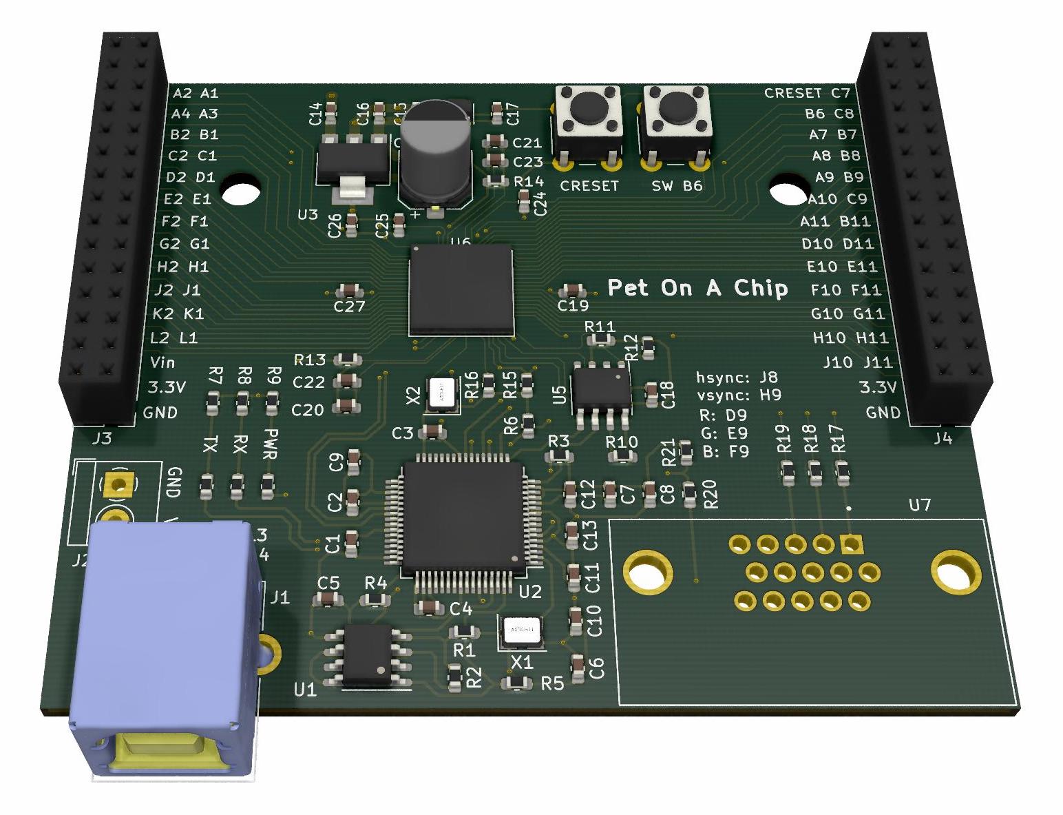
Pet on a chip is an open-source printed circuit board by ept221, from the ept221/pet-on-a-chip repository on GitHub, published under the MIT licence. It is a 4-layer board of 76.2 × 63.5 mm with 69 parts on 159 nets, routed with 1,058 tracks and 91 vias.
It is built around the ICE40HX8K-BG121, N25Q032A13ESC40F and FT2232HL, with the L77HDE15SD1CH4F, LDL1117S33R and TLV70012DDCR among its other parts. Its parts include 28 capacitors, 21 resistors, 7 ICs, 4 connectors and 3 diodes. It belongs with the robots and motor control and fPGA and programmable logic boards and the FPGA and CPLD boards of this library.


Pet on a chip is a project which condenses the control logic the robot described in Frank DaCosta's book "How to Build Your Own Working Robot Pet" onto a single FPGA. More details, pictures, and videos can be found on this blog post.
tinySoC is a small system on a chip responsible for controlling the robot. It consists of an 8-bit CPU, an 80 column VGA graphics controller, a programmable interrupt controller, GPIO, counter/timer peripherals, dual closed loop motor controllers, a servo controller, a sonar controller, and a UART, all implemented on an iCE40 FPGA. It also comes with an assembler and utilities for loading programs into the chip's internal block memory without having to rerun synthesis and place-and-route.
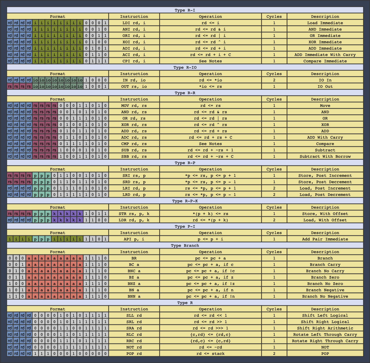
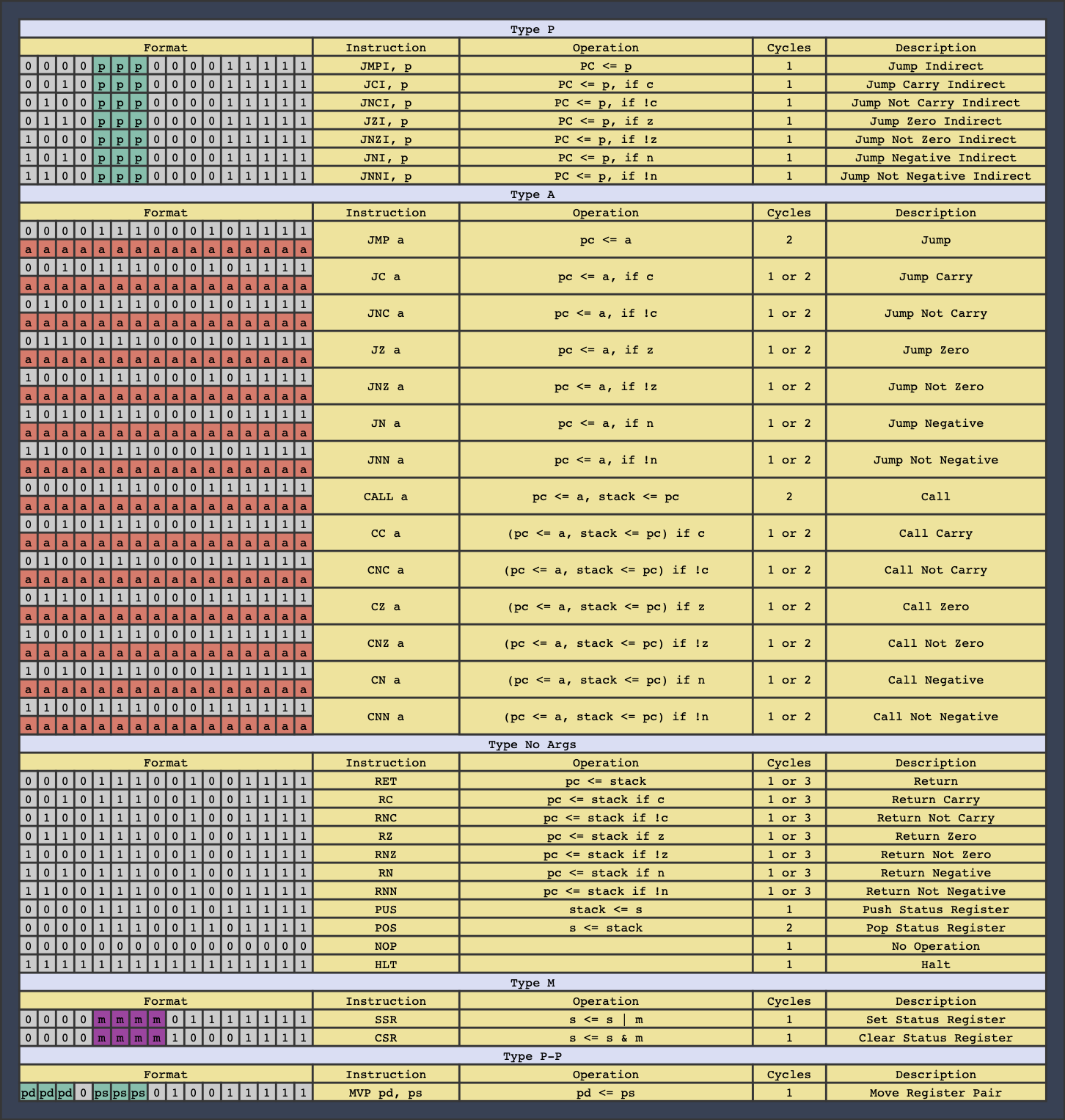
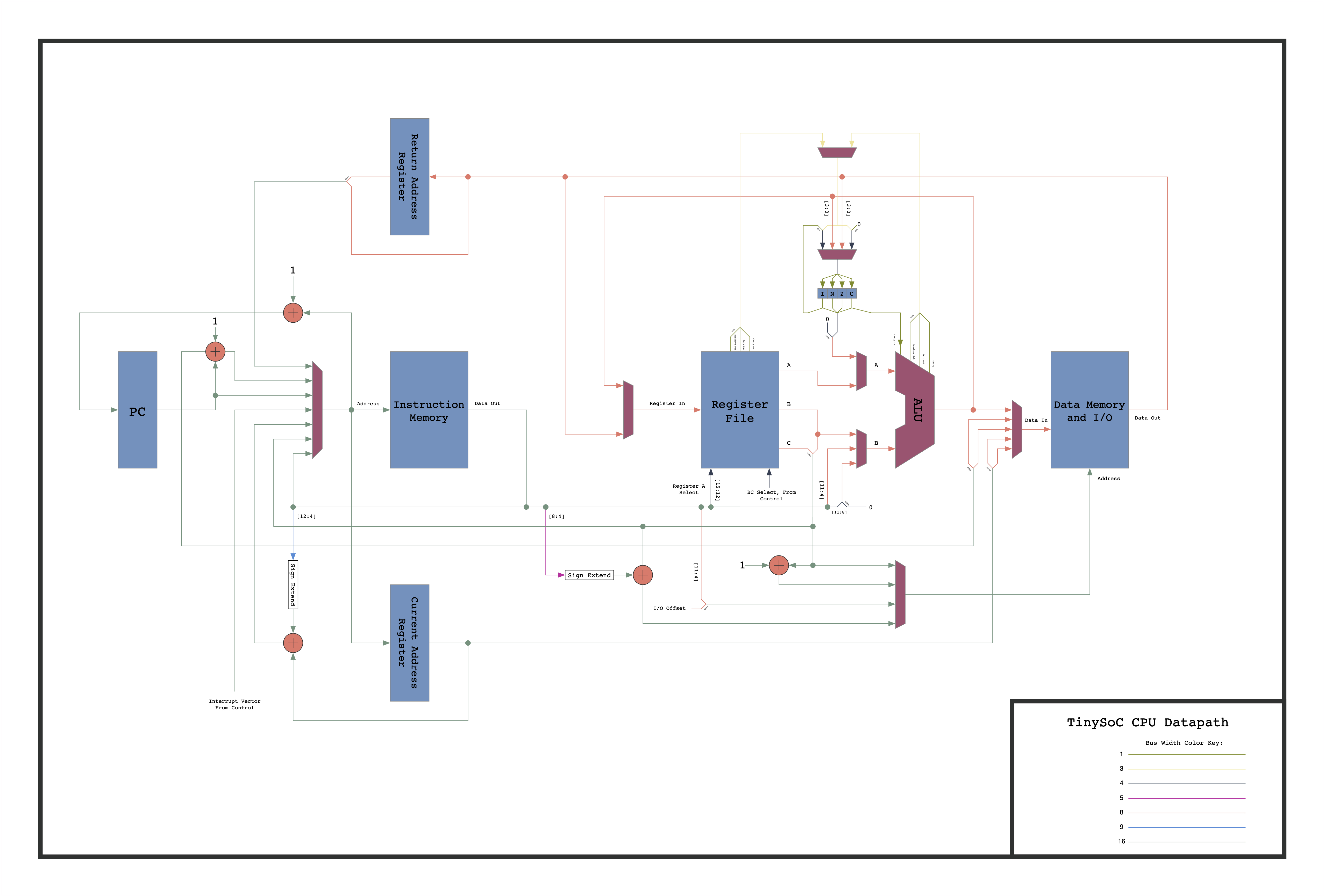 The CPU is an 8-bit RISC core, with a Harvard architecture. It has a 16-bit wide instruction memory, an 8-bit wide data memory, and both have a 16-bit address. The CPU has 16 general purpose 8-bit registers along with a 4-bit status register. The processor is not fully pipelined, but does fetch the next instruction while executing the current one. Most instructions execute in a single clock cycle, but a few take two or three.
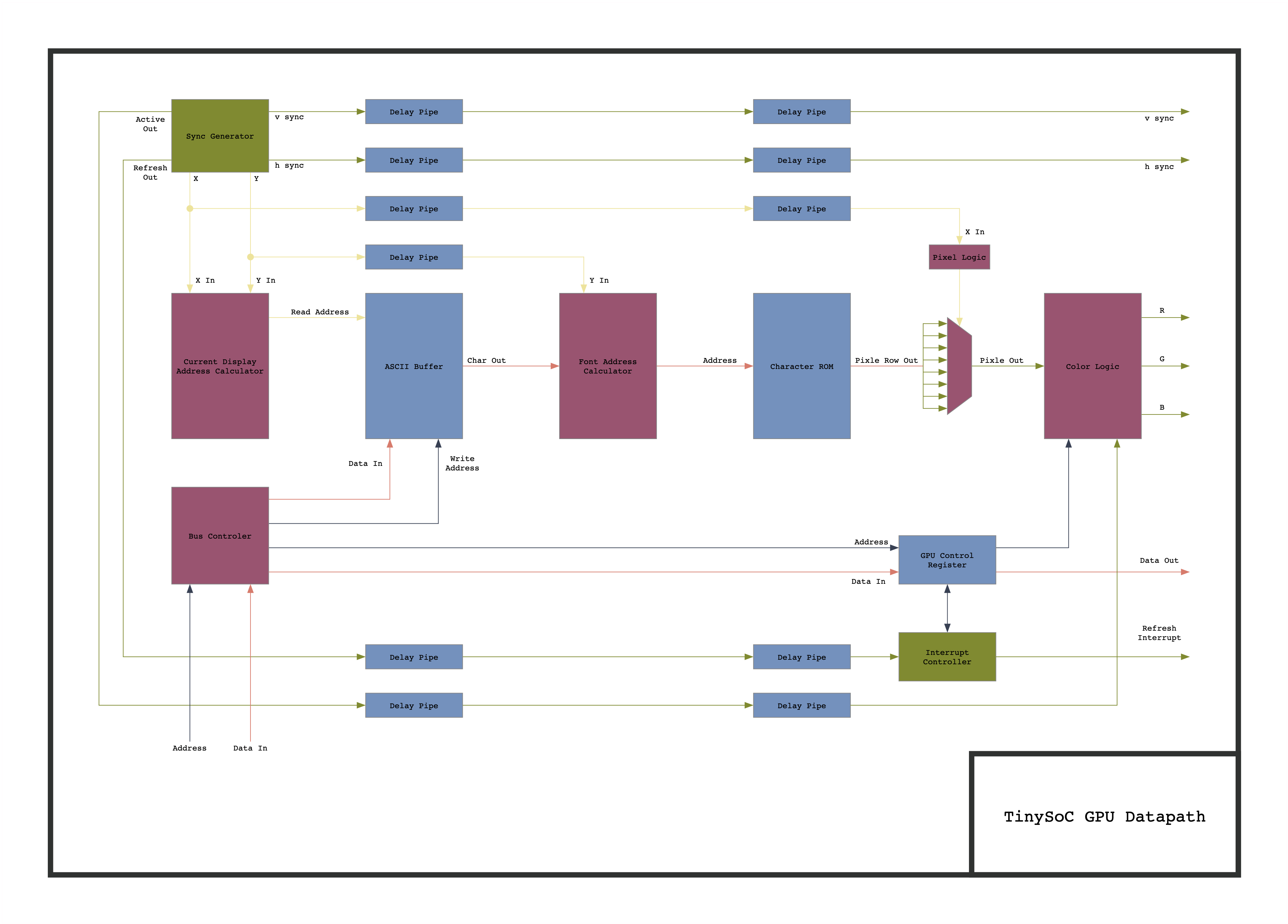 The GPU operates in a monochrome 80 column text mode, and outputs a VGA signal at a resolution of 640 by 480 at 60 frames per second. The GPU contains an ASCII buffer which the user can write to in order to display messages on the screen. A control register allows the user to set the text to one of 7 colors, and to enable an interrupt to the CPU which fires every time a frame finishes and enters the blanking period. Not shown in the diagram is control logic that allows the screen to be scrolled upwards by writing to the control register.
The main board:
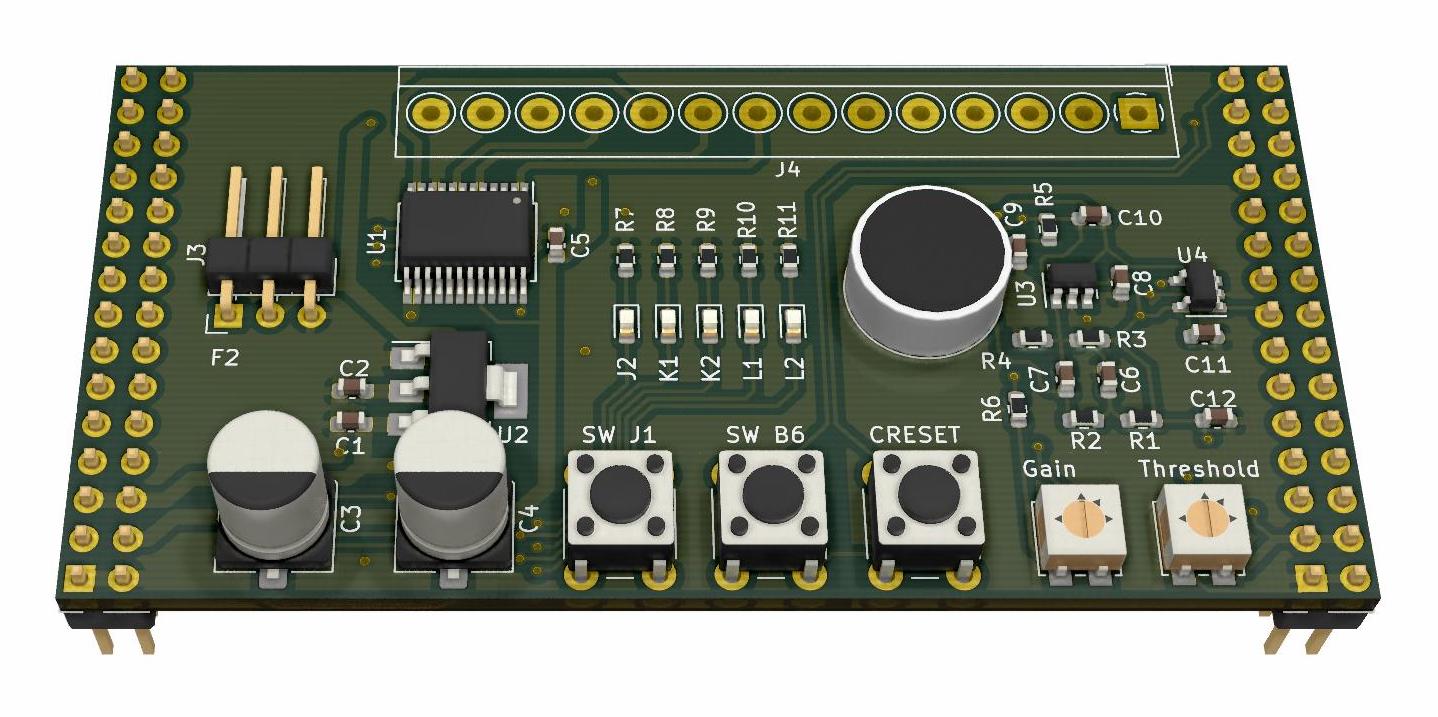
 The expantion board:
The assembler is case insensitive.
Comments begin with semicolons.
        .code
        ldi r0, 1 ; This is a comment
Constants are in decimal by default, but hexadecimal and binary are also supported. Constants can also be negative and are stored in two's complement form when assembled. Chars can also be entered as constants.
        .code
        ldi r0, 10     ; Decimal constant
        ldi r0, 0x0A   ; Hexadecimal constant
        ldi r0, 0b1010 ; Binary constant
        ldi r0, -10    ; A negative constant
        ldi r0, 'a'    ; A char constant
        ldi r0, '\n'   ; An escaped char constant
Label definitions may be any string ending with a colon, as long as the string is not in the form of a constant or is one of the reserved keywords
        .code
        ldi r0, 10
loop:   adi r0, -1
        bnz loop
hltSpecifies that the following lines are code to be assembled and placed in instruction memory.
Specifies that the following lines are data to be placed in data memory.
Sets the origin to the given address. Only forward movement of the origin is permitted.
        .code
        ldi r0, 1
        out r0, 0
        br foo

        .org 0x0B
foo:    out r0, 1
        hlt

;*************************************************************************
; Assembles to the following:
; Address        Label          Code                     Source
; ------------------------------------------------------------------------
; 0x0000                        0b0000000000010001       LDI R0, 1
; 0x0001                        0b0000000000001001       OUT R0, 0
; 0x0002                        0b0000000010011110       BR FOO
; 0x000B         FOO:           0b0000000000011001       OUT R0, 1
; 0x000C 0b1111111111111111 HLT Writes one or more data bytes sequentially into data memory.
        .data
        .db 0x01, 0x44, 0x73

;*************************************************************************
; Assembles to the following:
; Address        Label          Data
; ------------------------------------------
; 0x0000                        0x01
; 0x0001                        0x44
; 0x0002 0x73Defines a block of space in the data memory. This is useful for allocating room for a buffer.
        .data
        .db 5
        .ds 3
        .db 7

;*************************************************************************
; Assembles to the following:
; Address        Label          Data
; ------------------------------------------
; 0x0000                        0x05
; 0x0004 0x07 Writes a null terminated ASCII string into data memory. Double quotes and backslashes must be escaped with a backslash.
        .data
        .string "The robot says \"Hi!\""

;*************************************************************************
; Assembles to the following:
; Address        Label          Data
; ------------------------------------------
; 0x0000                        0x54
; 0x0001                        0x68
; 0x0002                        0x65
; 0x0003                        0x20
; 0x0004                        0x72
; 0x0005                        0x6F
; 0x0006                        0x62
; 0x0007                        0x6F
; 0x0008                        0x74
; 0x0009                        0x20
; 0x000A                        0x73
; 0x000B                        0x61
; 0x000C                        0x79
; 0x000D                        0x73
; 0x000E                        0x20
; 0x000F                        0x22
; 0x0010 0x48Write a ASCII string into data memory. The string is open, which means that it is not null terminated. This is useful if you have a long string that you want to split up into multiple lines in the assembly source file.
        .data
        .ostring "Hi! "
        .string  "Bye!"

;*************************************************************************
; Assembles to the following:
; Address        Label          Data
; ------------------------------------------
; 0x0000                        0x48
; 0x0001                        0x69
; 0x0002                        0x21
; 0x0003                        0x20
; 0x0004                        0x42
; 0x0005                        0x79
; 0x0006                        0x65
; 0x0007                        0x21
; 0x0008 0x00Equates a symbol with a number.
        .code
        .define foo, 5
        ldi r0, foo
        hlt

;*************************************************************************
; Assembles to the following:
; Address        Label          Code                     Source
; ------------------------------------------------------------------------
; 0x0000                        0b0000000001010001       LDI R0, FOO
; 0x0001 0b0000000011110000 HLT Any time an instruction or directive requires a numerical argument, an expression can be used. Supported operations inside expressions include addition and subtraction. The location counter $ is also made available. If an instruction is two bytes long then $ refers to the address of the second byte. Expressions may contain symbols, but must resolve within two passes of the assembler, and if used for directive arguments, must resolve in a single pass.
; Example resolution in one pass
        .code
        .define foo, 5
        ldi r0, foo + 7
        hlt

;*************************************************************************
; Assembles to the following:
; Address        Label          Code                     Source
; ------------------------------------------------------------------------
; 0x0000                        0b0000000011000001       LDI R0, FOO + 7
; 0x0001 0b0000000011110000 HLT; Example resolution in two passes
.code
ldi r0, foo + 7
hlt
.define foo, 5
;*************************************************************************
; Assembles to the following:
; Address Label Code Source
; ------------------------------------------------------------------------
; 0x0000 0b0000000011000001 LDI R0, FOO + 7
; 0x0001 0b0000000011110000 HLT; Example resolution in two passes with $
.code
ldi r0, $
jmp $ + foo
.define foo, 2
nop
nop
nop
hlt
;*************************************************************************
; Assembles to the following:
; Address Label Code Source
; ------------------------------------------------------------------------
; 0x0000 0b0000000000000001 LDI R0, $
; 0x0001 0b0000000010111000 JMP $ + FOO
; 0x0002 0b0000000000000100
; 0x0003 0b0000000000000000 NOP
; 0x0004 0b0000000000000000 NOP
; 0x0005 0b0000000000000000 NOP
; 0x0006 0b0000000011110000 HLTTo perform synthesis and place-and-route, run:
make synth
make pnr
To assemble a demo program, run:
./assemble programs/shell.asm shellTo upload the configuration bitstream for the previously assembled program, run:
./upload shellYou will now be able to interact with a basic shell over the UART at 115200 baud. Additionally, the output will also be sent over the VGA interface.
There are a variety of memory mapped peripherals included in the system. The memory map is configured in soc/src/d_ram_and_io/d_ram_and_io.v. Currently addresses 0x0000 to 0x07FF are mapped to data ram. The peripherals are mapped from 0x1000 to 0x10FF. The instructions in and out are designed to allow for quickly and easily reading and writing to peripherals within this address range. For example, out r1, 5 writes the value in r1 to address 0x1005. In contrast, when reading and writing to data memory, or writing to the graphics buffer which is from 0x2000 to 0x2960, in and out cannot be used, and the other load and store instructions must be used instead, which require setting up a pointer in a register pair to the memory location you want to operate on.
| Address | Register | r/w | Description |
|---|---|---|---|
| 0x1000 | Direction | r/w | Sets GPIO pins to input or output |
| 0x1001 | Port | r/w | Write values to be outputed |
| 0x1002 | Pin | r | Read values on pins |
| Address | Register | r/w | Description |
|---|---|---|---|
| 0x1003 | Scale LSB | r/w | |
| 0x1004 | Scale MSB | r/w | |
| 0x1005 | Control | r/w | |
| 0x1006 | CMPR0 | r/w | |
| 0x1007 | CMPR1 | r/w | |
| 0x1008 | Counter | r |
| Address | Register | r/w | Description |
|---|---|---|---|
| 0x1009 | Baud | r/w | Configures the baudrate |
| 0x100A | Status | r | Signals empty tx buffer and or full rx buffer |
| 0x100B | Buffer | r/w | Write to tx buffer, read from rx buffer |
| Address | Register | r/w | Description |
|---|---|---|---|
| 0x100C | Control | r/w | Sets the motors' directions |
| 0x100D | Enable | r/w | Enables the motor driver |
| 0x100E | Speed 0 | r/w | Target speed of motor 0 |
| 0x100F | Speed 1 | r/w | Target speed of motor 1 |
| 0x1010 | RPM 0 | r | Actual speed of motor 0 |
| 0x1011 | RPM 1 | r | Actual speed of motor 1 |
| Address | Register | r/w | Description |
|---|---|---|---|
| 0x1012 | Position | r/w | Sets the position of the servo |
| Address | Register | r/w | Description |
|---|---|---|---|
| 0x1013 | Status | r | Signals new reading in range register |
| 0x1014 | Range | r | Holds the measured distance |
| Address | Register | r/w | Description |
|---|---|---|---|
| 0x1015 | Vect 0 Low | r/w | LSBs of interrupt vector 0 |
| 0x1016 | Vect 0 High | r/w | MSBs of interrupt vector 0 |
| 0x1017 | Vect 1 Low | r/w | LSBs of interrupt vector 1 |
| 0x1018 | Vect 1 High | r/w | MSBs of interrupt vector 1 |
| 0x1019 | Vect 2 Low | r/w | LSBs of interrupt vector 2 |
| 0x101A | Vect 2 High | r/w | MSBs of interrupt vector 2 |
| 0x101B | Vect 3 Low | r/w | LSBs of interrupt vector 3 |
| 0x101C | Vect 3 High | r/w | MSBs of interrupt vector 3 |
| Qty | Value | Footprint | References |
|---|---|---|---|
| 16 | 0.1µF | Capacitor_SMD:C_0603_1608Metric | C1, C3, C4, C5, C6, C7, C8, C9, C11, C13, C18, C19, C24, C25, C26, C27 |
| 5 | 10K | Resistor_SMD:R_0603_1608Metric | R10, R11, R12, R15, R16 |
| 4 | 10k | Resistor_SMD:R_0603_1608Metric | R1, R4, R5, R21 |
| 4 | 1k | Resistor_SMD:R_0603_1608Metric | R6, R7, R8, R9 |
| 3 | 1µF | Capacitor_SMD:C_0603_1608Metric | C14, C15, C17 |
| 3 | 270 | Resistor_SMD:R_0603_1608Metric | R17, R18, R19 |
| 3 | 4.7µF | Capacitor_SMD:C_0603_1608Metric | C10, C12, C16 |
| 3 | LED | Resistor_SMD:R_0603_1608Metric | D1, RX1, TX1 |
| 2 | 100 | Resistor_SMD:R_0603_1608Metric | R13, R14 |
| 2 | 100nF | Capacitor_SMD:C_0603_1608Metric | C22, C23 |
| 2 | 10µF | Capacitor_SMD:C_0603_1608Metric | C20, C21 |
| 2 | ASTX-H11 | Oscillator:Oscillator_SMD_Abracon_ASE-4Pin_3.2x2.5mm | X1, X2 |
| 2 | Conn_02x15_Odd_Even | Connector_PinHeader_2.54mm:PinHeader_2x15_P2.54mm_Vertical | J3, J4 |
| 2 | SW_Push | Button_Switch_THT:SW_PUSH_6mm | SW1, SW2 |
| 1 | 12k | Resistor_SMD:R_0603_1608Metric | R3 |
| 1 | 2.2k | Resistor_SMD:R_0603_1608Metric | R2 |
| 1 | 3.3µF | Capacitor_SMD:C_0603_1608Metric | C2 |
| 1 | 4.7k | Resistor_SMD:R_0603_1608Metric | R20 |
| 1 | 470µF | Capacitor_SMD:CP_Elec_6.3x7.7 | C28 |
| 1 | 93LCxxC | Package_SO:SOIC-8_3.9x4.9mm_P1.27mm | U1 |
| 1 | FT2232HL | Package_QFP:LQFP-64_10x10mm_P0.5mm | U2 |
| 1 | ICE40HX8K-BG121 | Package_BGA:BGA-121_9.0x9.0mm_Layout11x11_P0.8mm_Ball0.4mm_Pad0.35mm_NSMD | U6 |
| 1 | L77HDE15SD1CH4F | pet on a chip:AMPHENOL_L77HDE15SD1CH4F | U7 |
| 1 | LDL1117S33R | Package_TO_SOT_SMD:SOT-223-3_TabPin2 | U3 |
| 1 | N25Q032A13ESC40F | Package_SO:SOP-8_3.9x4.9mm_P1.27mm | U5 |
| 1 | Screw_Terminal_01x02 | TerminalBlock_4Ucon:TerminalBlock_4Ucon_1x02_P3.50mm_Horizontal | J2 |
| 1 | TLV70012DDCR | Package_TO_SOT_SMD:SOT-23-5 | U4 |
| 1 | USB_B | Connector_USB:USB_B_OST_USB-B1HSxx_Horizontal | J1 |
The 67 most common of 69 parts.


cwillforeal/cwill_keyboard
Test Repo For messing around with keyboard things and the pico

Maillouski/Model-2-IO-Board-for-m2m3
Drop-in replacement for the Sega 837-10539 I/O board (Daytona USA twin, Model 2), built around an Arduino Mega 2560. KiCad 10, CC BY-NC-SA 4.0.

baldengineer/Mega-IIe
Using the Mega II from a IIgs to make a Apple IIe compatible computer: The Mega IIe!

Benny-Chippers/Enchanted_Rocks
The dev board PCB for the MacroController project

It measures 76.2 × 63.5 mm and has 4 copper layers, 1.6 mm thick.
69 parts, built around the ICE40HX8K-BG121, N25Q032A13ESC40F, FT2232HL and L77HDE15SD1CH4F. The full list of its parts is on this page, with links to each part's symbol and footprint where PCBKit's library has them.
From the ept221/pet-on-a-chip repository on GitHub, at the commit this page was made from: the board is pcb/pet on a chip/pet on a chip.kicad_pcb and its schematic pcb/daughter/daughter.kicad_sch. PCBKit opens the board in the browser, with nothing to install.
Its repository publishes it under the MIT licence: you may reuse it on that licence's terms (keep the author's notice, and for a copyleft licence share your changes alike).