
4 layers82.8 × 33 mm
E ink watch
sandgum/Triangulate-ES_01-Watch
A 5mm thick smartwatch which uses an E-ink display and two OLEDs to display information while consuming very little power
162 parts22

 Epivaral/CursoIoT3
Material complementario del curso: INTRODUCCIÓN A IOT, ALMACENAMIENTO EN LA NUBE Y ANÁLISIS DE DATA
Modulo 7 is an open-source printed circuit board by Epivaral, from the Epivaral/CursoIoT repository on GitHub. It is a 2-layer board of 44 × 88.2 mm with 11 parts on 33 nets, routed with 88 tracks and 1 via.
It is built around the MAX30102. Its parts include 3 switches, 2 resistors, 2 ICs and 1 connector. It belongs with the home automation and IoT boards and the ESP32 boards of this library.
Material complementario del curso: INTRODUCCIÓN A IOT, ALMACENAMIENTO EN LA NUBE Y ANÁLISIS DE DATA
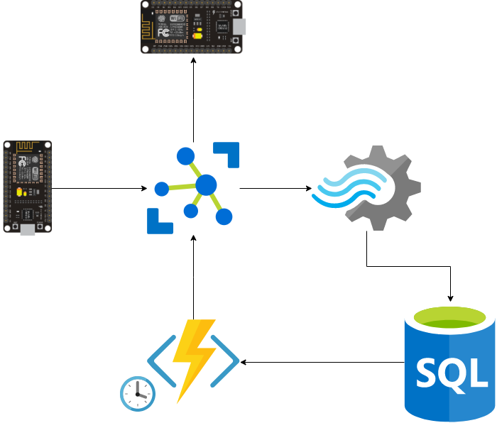
 Curso disponible aqui: Playlist Youtube
Modulos IoT para este curso, no necesitas todos, con un NodeMCU es mas que suficiente:
Material complementario Aqui ⬇
Material complementario Aqui ⬇
Material complementario Aqui ⬇
Material complementario Aqui ⬇
Material complementario Aqui ⬇
Material complementario Aqui ⬇
| Qty | Value | Footprint | References |
|---|---|---|---|
| 2 | 10K | Resistor_SMD:R_0805_2012Metric | R1, R2 |
| 1 | Batt | Connector_JST:JST_XH_B2B-XH-A_1x02_P2.50mm_Vertical | J1 |
| 1 | ESP32-DEVKIT-V1 | ESP32:MODULE_ESP32_DEVKIT_V1 | U1 |
| 1 | IP | Connector_Wire:SolderWire-0.25sqmm_1x02_P4.2mm_D0.65mm_OD1.7mm | SW3 |
| 1 | LOGO | Logos:spo2 | G*** |
| 1 | LOGO | Logos:heartRate | G*** |
| 1 | MAX30102 | Connector_PinSocket_2.54mm:PinSocket_1x04_P2.54mm_Vertical | U2 |
| 1 | PowerBatt | Connector_Wire:SolderWire-0.25sqmm_1x03_P4.2mm_D0.65mm_OD1.7mm | SW1 |
| 1 | SSD1306 | SSD1306:128x64OLED | Brd1 |
| 1 | WiFi | Connector_Wire:SolderWire-0.25sqmm_1x03_P4.2mm_D0.65mm_OD1.7mm | SW2 |
sandgum/Triangulate-ES_01-Watch
A 5mm thick smartwatch which uses an E-ink display and two OLEDs to display information while consuming very little power

theheraldproject/herald-hardware
Permissively licensed opensource hardware designs for Herald powered wearables and beacons. Supports digital contact tracing and other eHealth approaches.

abhinav937/RP2040_SOS_band
PCB design files for RP2040 based SmartWatch. It features an accelerometer, a GPS module and a cellular module.

Ghost3379/NX-ISD
A more sophisticated version of the Artemis Watch by Circuitmess.


Soham3126/DIY-SPO2-KiCAD-Project
A low-cost, non-invasive Pulse Oximeter (SpO2) and Heart Rate monitor based on the MAX30102 sensor and Arduino. This project features real-time PPG signal processing, I2C communication, and a custom PCB design for…

Taller-de-sistemas-embebidos-tps/tdse-tf_2-01
Trabajo Final - Taller de Sistemas Embebidos - FIUBA

It measures 44 × 88.2 mm and has 2 copper layers, 1.6 mm thick.
11 parts, built around the MAX30102. The full list of its parts is on this page, with links to each part's symbol and footprint where PCBKit's library has them.
From the Epivaral/CursoIoT repository on GitHub, at the commit this page was made from: the board is Modulo 7/PCB/PCB.kicad_pcb and its schematic Modulo 7/PCB/PCB.kicad_sch. PCBKit opens the board in the browser, with nothing to install.
Its repository states no licence, so its author keeps all rights: ask Epivaral before reusing the design.