2 layers45.2 × 87 mm
 emanuelen5/kitchen-timer
A digital kitchen timer made from scratch
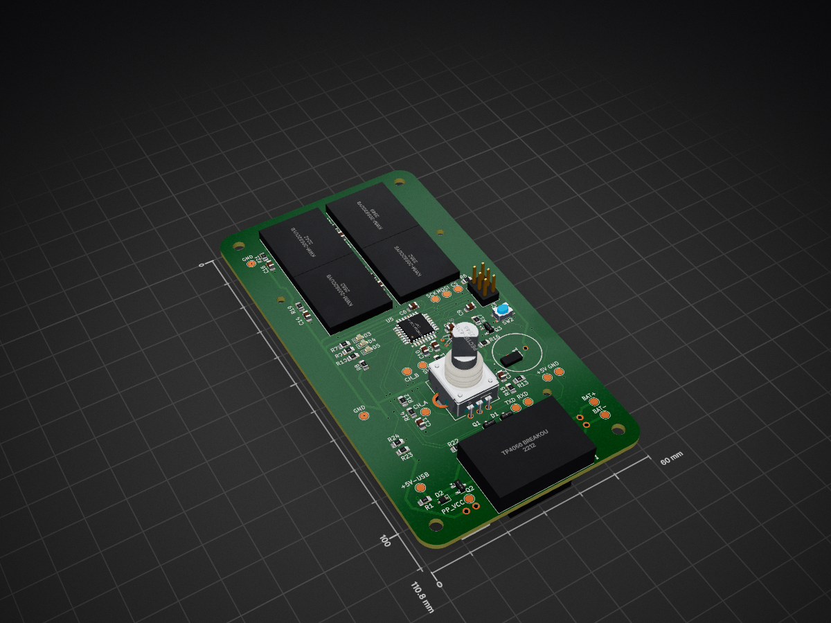
Kitchen timer hardware is an open-source printed circuit board by emanuelen5, from the emanuelen5/kitchen-timer repository on GitHub. It is a 2-layer board of 60 × 110.8 mm with 83 parts on 121 nets, routed with 938 tracks and 108 vias.
It is built around the ATMEGA328P-AU, MAX7219M and PEC11R-4215F-S0024, with the BAS40, IRLML6402 and JSM2302 among its other parts. Its parts include 20 resistors, 13 ICs, 12 capacitors, 5 diodes and 3 transistors. It belongs with the AVR (ATmega, ATtiny) boards of this library.


We're building a Kitchen timer! The project is heavily inspired by REST: Kitchen timer by mkdxdx [Hackaday.io].
See the bill of material in the KiCAD project for the full details.
Additionally, you will need the following mechanical components for the assembly:
| Description | Qty |
|---|---|
| Hexagon Socket Button Head Screw ISO 7380-1 - M3 x 16 | 4 |
| Hexagon Socket Button Head Screw ISO 7380-1 - M2 x | 3 |
| Brass Threaded Insert M3 | 4 |
| Brass Threaded Insert M2 | 3 |
| Hexagon Socket Button Head Screw ISO 7380-1 - M2 x | 3 |
| 3.7V Lipo battery 1000mAh, 10x20x50mm, JST XH2.54 2 pin | 1 |
If you want to build the PCB yourself, you can download the latest release of Gerber files from Github: https://github.com/emanuelen5/kitchen-timer/releases/latest
The .stl files are available in ./enclosure so you can 3D-print the enclosure yourself.
You can flash the program directly using the ISP header on the board if you want (the same procedure as flashing the bootloader, below). But it's more convenient to add the bootloader so you don't have to open up the enclosure for each software update. Then you can instead program it over the USB-C connector.
For that, you need the bootloader firmware and programmer software which you can download from https://github.com/emanuelen5/kitchen-timer/releases/tag/bootloader-v1.2.0.
To flash the microcontroller with the bootloader, you need avrdude.
Avrdude 7.3 can be downloaded from https://github.com/avrdudes/avrdude/releases/tag/v7.3. Make sure to add it to your PATH.
Connect your programmer of choice to the 6-pin in-system programmer (ISP) connector:
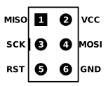
Then run the following command (replace <programmer> with your programmer of choice, like usbtiny):
# the bootloader.hex file needs to be in the current directory
avrdude -p atmega328p -c <programmer> -U flash:w:bootloader.hex:i \
  -U lfuse:w:0x62:m -U hfuse:w:0xD0:m -U efuse:w:0xFF:m
[!TIP] Use
avrdude -c ?to see which programmers are available
This flashes the bootloader and sets the required fuses for the bootloader.
After that you can disconnect the programmer and assemble the device.
Now that you have the bootloader on the device, you can use the USB-C cable for programming it by using the programmer application.
First you will need to install some packages that the programmer needs (files from https://github.com/emanuelen5/kitchen-timer/releases/tag/bootloader-v1.2.0).
pip install -r ./programmer/requirements.txtYou can now program the application onto the device through the bootloader!
Download the latest revision of the firmware (if you want to build it yourself, see #Development below) from the releases https://github.com/emanuelen5/kitchen-timer/releases.
Connect the USB cable to the device, and then run
python3 ./programmer/programmer.py --hexfile firmware.hexTo build the firmware, you need pio which can be downloaded from https://pypi.org/project/platformio/ or installed using pip (the official Package Installer for Python)
To build any of the environments, use the pio command, like
# builds the main application and puts it in .pio/builds/application/firmware.hex
pio run -e application
Then use the programmer to upload the firmware to the device.
Our kitchen timer is an iteration of mkdxdx project "REST: Kitchen timerREST: Kitchen timer". We wanted to keep the "dial" (rotate-to-set) concept and the 16x16 led matrix but do it with an ATmega328p and a custom PCB. In the end we scrapped the dial since the design became too complicated, and settled on a simpler design.
Both Erasmus Cedernaes and Nicolas Perozzi belong to Stockholm Makerspace. On the same day, we messaged each other a link to mkdxdx project. We were very excited about building something that would be "practical" so we decided to team up and work on this together. Additionally, we share an interest in working with the AVR MCUs. This project is a nice blend of programming, electrical, mechanical, 3d printing, and design but, without feeling overwhelming.
| Qty | Value | Footprint | References |
|---|---|---|---|
| 9 | 10k | Resistor_SMD:R_0805_2012Metric_Pad1.20x1.40mm_HandSolder | R1, R6, R8, R11, R12, R13, R14, R15, R22 |
| 7 | 100nF | Capacitor_SMD:C_0805_2012Metric_Pad1.18x1.45mm_HandSolder | C5, C6, C9, C13, C14, C15, C16 |
| 5 | 1k | Resistor_SMD:R_0805_2012Metric_Pad1.20x1.40mm_HandSolder | R7, R9, R10, R16, R17 |
| 4 | 62K | Resistor_SMD:R_0805_2012Metric_Pad1.20x1.40mm_HandSolder | R18, R19, R20, R21 |
| 4 | KWM-20882CUYB | kitchen_timer:KWM-20882CUYB | U11, U12, U13, U14 |
| 4 | MAX7219 | Package_SO:SOIC-24W_7.5x15.4mm_P1.27mm | U7, U8, U9, U10 |
| 4 | MountingHole | MountingHole:MountingHole_3.2mm_M3 | H3, H4, H5, H6 |
| 3 | 10nF | Capacitor_SMD:C_0805_2012Metric_Pad1.18x1.45mm_HandSolder | C10, C11, C12 |
| 3 | GND | TestPoint:TestPoint_Pad_D2.0mm | TP8, TP14, TP15 |
| 3 | MountingHole | MountingHole:MountingHole_2.2mm_M2 | H1, H2, H7 |
| 3 | Red test LED | LED_SMD:LED_0603_1608Metric_Pad1.05x0.95mm_HandSolder | D3, D4, D5 |
| 2 | 22pF | Capacitor_SMD:C_0805_2012Metric_Pad1.18x1.45mm_HandSolder | C7, C8 |
| 1 | +5V | TestPoint:TestPoint_Pad_D2.0mm | TP12 |
| 1 | +5V-USB | TestPoint:TestPoint_Pad_D2.0mm | TP7 |
| 1 | 1M | Resistor_SMD:R_0805_2012Metric_Pad1.20x1.40mm_HandSolder | R24 |
| 1 | 3.3M | Resistor_SMD:R_0805_2012Metric_Pad1.20x1.40mm_HandSolder | R23 |
| 1 | ATMEGA328P-AU | Package_QFP:TQFP-32_7x7mm_P0.8mm | U5 |
| 1 | AVR-ISP-6 | Connector_PinHeader_2.54mm:PinHeader_2x03_P2.54mm_Vertical | J3 |
| 1 | BAS40 | Package_TO_SOT_SMD:SOT-23 | D1 |
| 1 | BAT+ | TestPoint:TestPoint_Pad_D2.0mm | TP16 |
| 1 | BAT- | TestPoint:TestPoint_Pad_D2.0mm | TP17 |
| 1 | CH340E UART Module | kitchen_timer:CH340E_UART_BREAKOUT | U1 |
| 1 | CH_A | TestPoint:TestPoint_Pad_D2.0mm | TP9 |
| 1 | CH_B | TestPoint:TestPoint_Pad_D2.0mm | TP10 |
| 1 | CS | TestPoint:TestPoint_Pad_D2.0mm | TP5 |
| 1 | Conn_01x02 | kitchen_timer:JST_XH_1x02_P2.54mm_Vertical | J1 |
| 1 | Conn_01x02_Pin | kitchen_timer:JST_XH_1x02_P2.54mm_Vertical | J2 |
| 1 | Crystal-32kHz | Crystal:Crystal_C26-LF_D2.1mm_L6.5mm_Horizontal | Y1 |
| 1 | DTR | TestPoint:TestPoint_Pad_D2.0mm | TP6 |
| 1 | IRLML6402 | Package_TO_SOT_SMD:SOT-23 | Q2 |
| 1 | JSM2302 | Package_TO_SOT_SMD:SOT-23 | Q1 |
| 1 | MMBT3904 | kitchen_timer:MMBT3904 (SOT-23) | Q3 |
| 1 | MOSI | TestPoint:TestPoint_Pad_D2.0mm | TP1 |
| 1 | PEC11R-4215F-S0024 | kitchen_timer:PEC11R4215FS0024 | U6 |
| 1 | PMEG4010CEJ | Diode_SMD:D_SOD-323F | D2 |
| 1 | PP_VCC | TestPoint:TestPoint_Pad_D2.0mm | TP13 |
| 1 | PS1240P02CT3 | kitchen_timer:PS1240P02BT | LS1 |
| 1 | RXD | TestPoint:TestPoint_Pad_D2.0mm | TP4 |
| 1 | SCK | TestPoint:TestPoint_Pad_D2.0mm | TP3 |
| 1 | SKRPACE010 | kitchen_timer:SW_SKRPACE010 | SW2 |
| 1 | SW | TestPoint:TestPoint_Pad_D2.0mm | TP11 |
| 1 | SparkFun_LiPower | kitchen_timer:SparkFun_LiPower | U3 |
| 1 | TP4056 breakout | kitchen_timer:TP4056_BREAKOUT | U2 |
| 1 | TXD | TestPoint:TestPoint_Pad_D2.0mm | TP2 |
It measures 60 × 110.8 mm and has 2 copper layers, 1.6 mm thick.
83 parts, built around the ATMEGA328P-AU, MAX7219M, PEC11R-4215F-S0024 and BAS40. The full list of its parts is on this page, with links to each part's symbol and footprint where PCBKit's library has them.
From the emanuelen5/kitchen-timer repository on GitHub, at the commit this page was made from: the board is pcb/kitchen_timer-hardware.kicad_pcb and its schematic pcb/boost_converter.kicad_sch. PCBKit opens the board in the browser, with nothing to install.
Its repository states no licence, so its author keeps all rights: ask emanuelen5 before reusing the design.

mcqn/bike-head
Making your bike more fun (if that's possible) by giving it a head

dyu134/ESP-HI-PLUS
The Robot sub-module is a high-performance actuator and sensing expansion board for the ESP-HI-PLUS, designed to transform the device into a mobile or interactive robotic platform.

ahessling/ActiveLoad
Small 12 Watt Active Load (dummy load) with STM32 microcontroller


kitspace/component_tester
A keychain version of the Mikrontroller.net AVR component tester


DoImant/TP4056-Power-Path-PCB
TP4056 Power Sharing PCB. Charge battery despite connected load.