
2 layers68.6 × 53.3 mm
 Else156/AutomaticPresentationTimer
発表会で使用するプレゼンタイマーのプログラムと回路データを格納
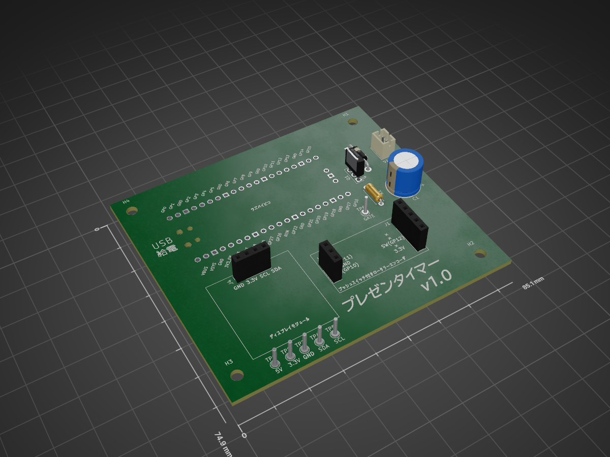
AutomaticPresentationTimer v1.0 is an open-source printed circuit board by Else156, from the Else156/AutomaticPresentationTimer repository on GitHub. It is a 2-layer board of 85.1 × 74.9 mm with 19 parts on 81 nets, routed with 85 tracks and 0 vias.
It is built around the 2SK4017(Q). Its parts include 4 connectors, 1 capacitor, 1 resistor, 1 IC and 1 diode. It belongs with the RP2040 boards of this library.
Raspberry Pi Pico、SSD1306 OLEDディスプレイ、ソレノイド、およびチンベルを使用したプレゼンテーションタイマーです。 設定した時間(例:予鈴、中間鈴、終了鈴)になると、物理的なベルを「チン!」と鳴らして知らせます。 操作にはRGBロータリーエンコーダを使用し、直感的なメニュー操作と時間設定が可能です。
| 部品名 | 型番 | URL | 備考 |
|---|---|---|---|
| Raspberry Pi Pico | SC0915 | 購入先URL | |
| 有機ELディスプレイ(OLED) 白色 | 購入先URL | ||
| イルミネーションロータリーエンコーダ用ピッチ変換基板 | SFE-BOB-11722 | 購入先URL | 廃盤だが千石電商では販売(2026年1月時点) |
| ソレノイド | ZHO-0420S-05A4.5(5V) | 購入先URL | |
| NchパワーMOSFET | 2SK4017(Q) | 購入先URL | |
| カーボン抵抗 10kΩ | RD25S 10K | 購入先URL | |
| 汎用整流用ダイオード 1000V1A | 1N4007-B | 購入先URL | |
| 電解コンデンサー1000μF35V | 35ZLH1000MEFC12.5X20 | 購入先URL | |
| チェック端子(テストポイント) | TEST-22 | 購入先URL | |
| チンベル(卓上ベル) |
hardware.py のデフォルト設定に基づく配線図です。
| 部品 | ピン名 | Pico GPIO | 備考 |
|---|---|---|---|
| OLED (I2C) | SDA | GP0 | |
| SCL | GP1 | ||
| VCC/GND | - | 3.3V / GND | |
| Encoder | A相 (CLK) | GP10 | Pull-Up設定 |
| B相 (DT) | GP11 | Pull-Up設定 | |
| Switch (SW) | GP12 | Pull-Up設定 (Active Low) | |
| GND | - | 共通GND | |
| Solenoid | Gate/Base | GP15 | 要ドライバ回路 |
[!WARNING] 警告: ソレノイドをGPIOピン(GP15)に直接接続しないでください。過電流と逆起電力によりPicoが破損します。必ずMOSFET等を使用したドライバ回路と、保護用ダイオードを組み込んでください。
プロジェクトは機能ごとにモジュール化されています。
.
├── circuit/                               # 回路設計関連
│   ├── AutomaticPresentationTimer_v1.0    # Kicadデータが格納
|   └── library/KiCad-RP-Pico-main         # Kicadでの使用ライブラリが格納
├── src/                       # ソースコード
│   ├── main.py                # エントリーポイント。状態遷移と設定の保存/読込を管理
│   ├── hardware.py            # GPIO制御(ソレノイド、エンコーダ、ボタン)
│   ├── display.py             # SSD1306への描画処理
│   ├── presentation_timer_mode.py # タイマー計測・実行モードのロジック
│   ├── setting_mode.py        # メニュー選択モードのロジック
│   ├── edit_mode.py           # 時間設定変更モードのロジック
|   └── settings.json          # 設定保存ファイル (初回実行時に自動生成)
└── README.md
[!WARNING] 警告: プログラムを実行する場合は、ディスプレイ用ドライバライブラリとしてssd1306.pyを得る必要があります。
| Qty | Value | Footprint | References |
|---|---|---|---|
| 4 | MountingHole | MountingHole:MountingHole_3.2mm_M3 | H1, H2, H3, H4 |
| 1 | 1000µF 35V | Capacitor_THT:CP_Radial_D10.0mm_P5.00mm | C1 |
| 1 | 10k | Resistor_THT:R_Axial_DIN0207_L6.3mm_D2.5mm_P7.62mm_Horizontal | R1 |
| 1 | 2SK4017 | Package_TO_SOT_THT:TO-251-3_Vertical | Q1 |
| 1 | 3.3V | TestPoint:TestPoint_THTPad_D2.0mm_Drill1.0mm | TP2 |
| 1 | 5V | TestPoint:TestPoint_THTPad_D2.0mm_Drill1.0mm | TP1 |
| 1 | Conn_01x03 | Connector_PinSocket_2.54mm:PinSocket_1x03_P2.54mm_Vertical | J2 |
| 1 | Conn_01x05 | Connector_PinSocket_2.54mm:PinSocket_1x05_P2.54mm_Vertical | J1 |
| 1 | D | Diode_THT:D_DO-41_SOD81_P10.16mm_Horizontal | D1 |
| 1 | GATE | TestPoint:TestPoint_THTPad_D2.0mm_Drill1.0mm | TP6 |
| 1 | GND | TestPoint:TestPoint_THTPad_D2.0mm_Drill1.0mm | TP3 |
| 1 | Pico | MCU_RaspberryPi_and_Boards:RPi_Pico_SMD_TH | U1 |
| 1 | SCL | TestPoint:TestPoint_THTPad_D2.0mm_Drill1.0mm | TP5 |
| 1 | SDA | TestPoint:TestPoint_THTPad_D2.0mm_Drill1.0mm | TP4 |
| 1 | ZHO-0420S-05A4.5(5V) | Connector_JST:JST_PH_B2B-PH-K_1x02_P2.00mm_Vertical | J3 |
| 1 | ディスプレイモジュール | Connector_PinSocket_2.54mm:PinSocket_1x04_P2.54mm_Vertical | J4 |
It measures 85.1 × 74.9 mm and has 2 copper layers, 1.6 mm thick.
19 parts, built around the 2SK4017(Q). The full list of its parts is on this page, with links to each part's symbol and footprint where PCBKit's library has them.
From the Else156/AutomaticPresentationTimer repository on GitHub, at the commit this page was made from: the board is circuit/AutomaticPresentationTimer_v1.0/AutomaticPresentationTimer_v1.0.kicad_pcb and its schematic circuit/AutomaticPresentationTimer_v1.0/AutomaticPresentationTimer_v1.0.kicad_sch. PCBKit opens the board in the browser, with nothing to install.
Its repository states no licence, so its author keeps all rights: ask Else156 before reusing the design.

Dudestin/tinyEtherDeveloper
Inexpensive FPGA board-based Ethernet evaluation board project. Consists mostly of DIP components and uses Tang PriMER. It can be built for about $50.


noritama-lab/esp32io-hw
ESP32 ベースの I/O ボードのハードウェア設計をまとめたリポジトリです。 / Hardware designs for an ESP32‑based PLC‑compatible I/O board.


0kam/ShutterClock
Low-power BLE interval timer for fixed-point Nikon DSLR cameras (XIAO nRF52840, Zephyr, Web Bluetooth)

0kam/SnowGauge
Low-cost, low-power snow depth logger for remote subalpine monitoring (NIR laser ToF + XIAO nRF52840 Sense)

airpocket-soundman/chikuwa-flute-robot
学習では、あらかじめ作った 1,000 曲のセット(runs/targetbank.npz、trainresiduales.py --bank 1000 で自動作成)から毎世代 8 曲を選んで使い回します。評価用の曲は別の乱数で作るので、学習用と重なりません。セットの中身は WAV と図で確認できます: