


2 layers100 × 100 mm
Pico router backup
Dudestin/tinyEtherDeveloper
Inexpensive FPGA board-based Ethernet evaluation board project. Consists mostly of DIP components and uses Tang PriMER. It can be built for about $50.
98 parts2
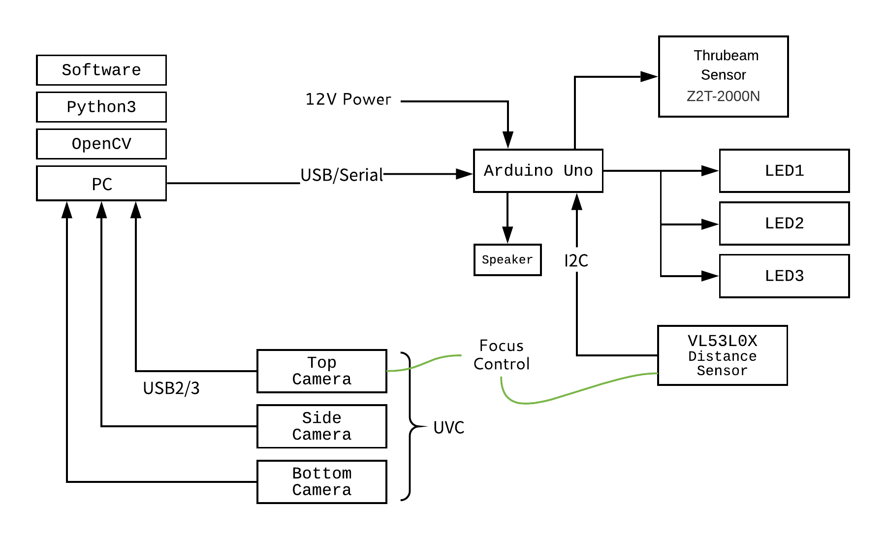
高速な書影撮影システム「オープンブックカメラ」
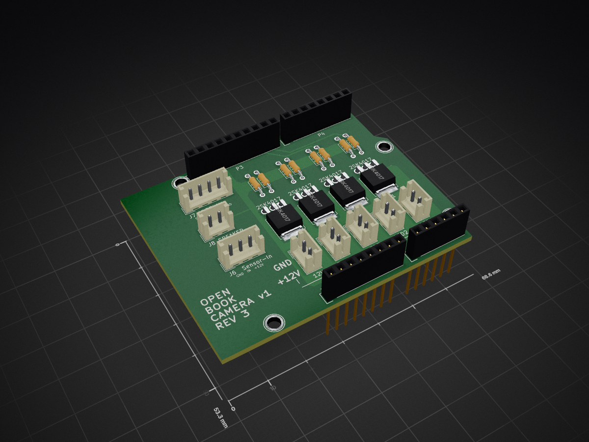
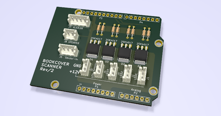
Shoei is an open-source printed circuit board by CALIL, from the CALIL/openbookcamera repository on GitHub, published under the MIT licence. It is a 2-layer board of 68.6 × 53.3 mm with 28 parts on 42 nets, routed with 82 tracks and 0 vias.
It is built around the 2SK4017(Q) and VL53L0X. Its parts include 16 connectors, 8 resistors and 4 diodes.
汎用的なデバイスで構成される高速な書影撮影システム
Windows:
conda install opencv==3.4.2
pip install -r requirements.txt
python capture.py| キー | 役割 |
|---|---|
| 0 | コントローラーリセット |
| 1 | 上面のカメラに切り替える |
| 2 | 下面のカメラに切り替える |
| 3 | 背面のカメラに切り替える |
| 4 | 距離センサのテスト |
| c | カメラの設定画面を開く |
| ESC | システム終了 |
| Enter | 手動撮影 |
1→c 2→c と操作することで各カメラの設定を順次調整できます。調整結果は保存されません。
| Qty | Value | Footprint | References |
|---|---|---|---|
| 4 | 100k | Resistor_THT:R_Axial_DIN0204_L3.6mm_D1.6mm_P7.62mm_Horizontal | R5, R6, R7, R8 |
| 4 | 2SK4017 | Package_TO_SOT_THT:TO-251-3-1EP_Horizontal_TabDown | D1, D2, D3, D4 |
| 4 | 300 | Resistor_THT:R_Axial_DIN0204_L3.6mm_D1.6mm_P7.62mm_Horizontal | R1, R2, R3, R4 |
| 4 | CONN_01X01 | Socket_Arduino_Uno:Arduino_1pin | P5, P6, P7, P8 |
| 1 | 12V | Connector_JST:JST_EH_B02B-EH-A_1x02_P2.50mm_Vertical | J5 |
| 1 | Analog | Socket_Arduino_Uno:Socket_Strip_Arduino_1x06 | P2 |
| 1 | Digital | Socket_Arduino_Uno:Socket_Strip_Arduino_1x08 | P4 |
| 1 | Digital | Socket_Arduino_Uno:Socket_Strip_Arduino_1x10 | P3 |
| 1 | LED1 | Connector_JST:JST_EH_B02B-EH-A_1x02_P2.50mm_Vertical | J1 |
| 1 | LED2 | Connector_JST:JST_EH_B02B-EH-A_1x02_P2.50mm_Vertical | J2 |
| 1 | LED3 | Connector_JST:JST_EH_B02B-EH-A_1x02_P2.50mm_Vertical | J3 |
| 1 | Power | Socket_Arduino_Uno:Socket_Strip_Arduino_1x08 | P1 |
| 1 | SPEAKER | Connector_JST:JST_EH_B02B-EH-A_1x02_P2.50mm_Vertical | J8 |
| 1 | Sensor | Connector_JST:JST_EH_B02B-EH-A_1x02_P2.50mm_Vertical | J4 |
| 1 | Sensor-In | Connector_JST:JST_EH_B03B-EH-A_1x03_P2.50mm_Vertical | J6 |
| 1 | VL53L0X | Connector_JST:JST_EH_B04B-EH-A_1x04_P2.50mm_Vertical | J7 |
It measures 68.6 × 53.3 mm and has 2 copper layers, 1.6 mm thick.
28 parts, built around the 2SK4017(Q) and VL53L0X. The full list of its parts is on this page, with links to each part's symbol and footprint where PCBKit's library has them.
From the CALIL/openbookcamera repository on GitHub, at the commit this page was made from: the board is controller/circuit/shoei.kicad_pcb. PCBKit opens the board in the browser, with nothing to install.
Its repository publishes it under the MIT licence: you may reuse it on that licence's terms (keep the author's notice, and for a copyleft licence share your changes alike).
Dudestin/tinyEtherDeveloper
Inexpensive FPGA board-based Ethernet evaluation board project. Consists mostly of DIP components and uses Tang PriMER. It can be built for about $50.


noritama-lab/esp32io-hw
ESP32 ベースの I/O ボードのハードウェア設計をまとめたリポジトリです。 / Hardware designs for an ESP32‑based PLC‑compatible I/O board.


0kam/ShutterClock
Low-power BLE interval timer for fixed-point Nikon DSLR cameras (XIAO nRF52840, Zephyr, Web Bluetooth)

0kam/SnowGauge
Low-cost, low-power snow depth logger for remote subalpine monitoring (NIR laser ToF + XIAO nRF52840 Sense)

airpocket-soundman/chikuwa-flute-robot
学習では、あらかじめ作った 1,000 曲のセット(runs/targetbank.npz、trainresiduales.py --bank 1000 で自動作成)から毎世代 8 曲を選んで使い回します。評価用の曲は別の乱数で作るので、学習用と重なりません。セットの中身は WAV と図で確認できます:
