4 layers83 × 100 mm

 elektrojupp/AD9954_TESTBOARD3
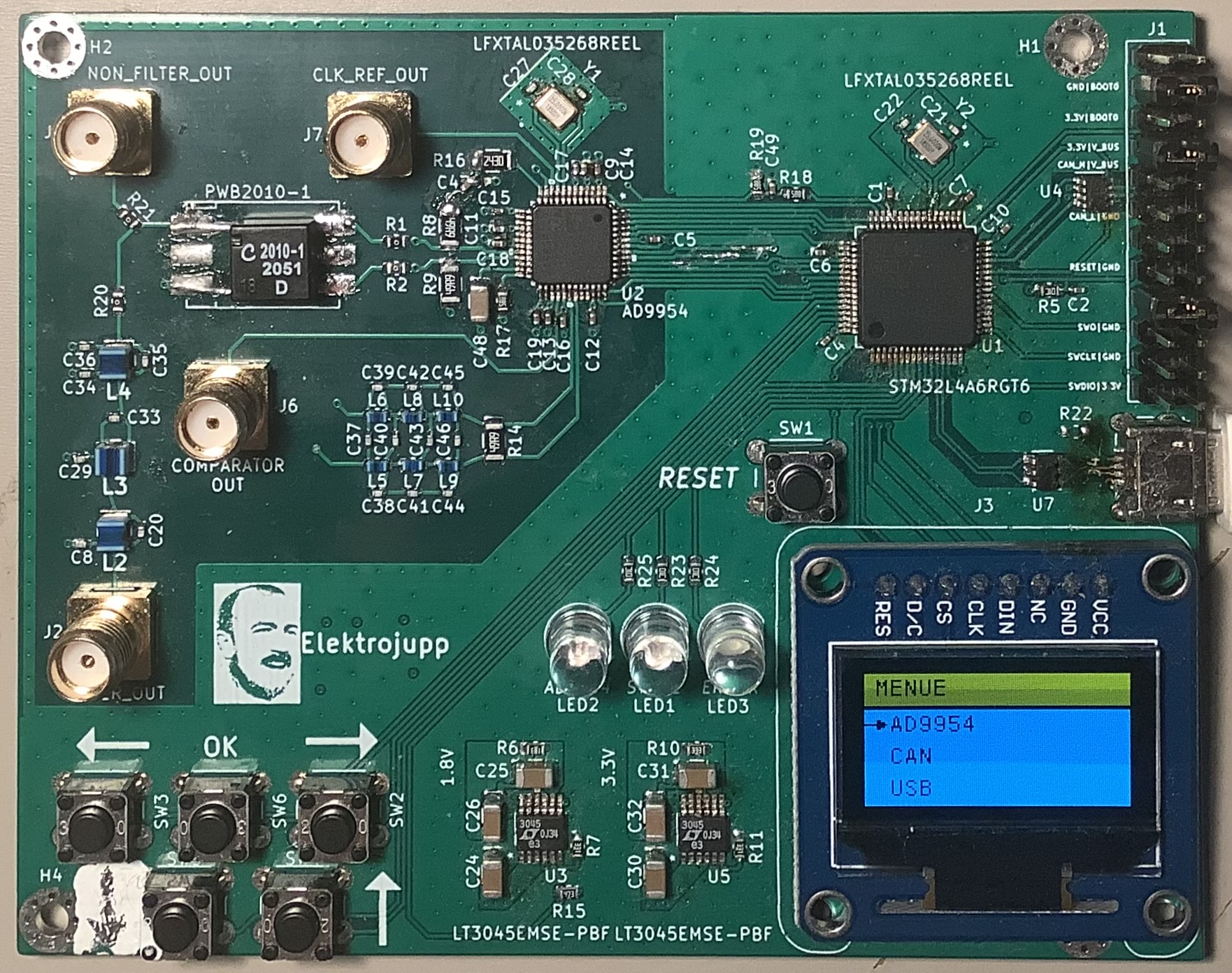
Testboard for AD9954 controlled by a STM32L4. Available interfaces: SWD, CAN, USB and GUI
AD9954 TESTBOARD is an open-source printed circuit board by elektrojupp, from the elektrojupp/AD9954_TESTBOARD repository on GitHub, published under the GPL-3.0 licence. It is a 4-layer board of 100 × 80 mm with 123 parts on 93 nets, routed with 1,161 tracks and 693 vias.
It is built around the STM32L4A6RGT6, TCAN330D and AD9954YSV, with the USBLC6-2SC6 and LFXTAL035268REEL among its other parts. Its parts include 48 capacitors, 25 resistors, 9 inductors, 7 connectors and 6 ICs. It belongs with the interfaces and adapters boards and the STM32 boards of this library.


Testboard for AD9954 controlled by a STM32L4. Available interfaces: SWD, CAN, USB and GUI
Hardware folder contains PCB in as Kicad project. All used components/footprints/3D models in project specific libary, so it should be possible to open without problems.
Software folder contains a STM32CubeIDE project. For compilation it might be necessary to have the STM32L4 support package installed. All interfaces are accessible via software: AD9954 can run in single tone mode, USB runs as loopserver, CAN interface initiates (no further testing). GUI menue structure is a bit blown up but flexible. STM32L4 runs FREERTOS RTOS. Every interface has its own task. Communication over queues and semaphores, between different tasks, so its possible to implement communication over USB/CAN to AD9954. When a button is pressed during RESET, a snake game appears. Speacial feature of the snake game is to store the highscore in flash (simple eeprom emulation).
More Pictures in Picture folder
| Qty | Value | Footprint | References |
|---|---|---|---|
| 18 | 100n | fg_proj:C_0402_1005Metric | C1, C2, C4, C5, C6, C10, C11, C12, C13, C14, C15, C16, C17, C18, C19, C49 +2 |
| 6 | 0 | fg_proj:R_0603_1608Metric | R1, R2, R12, R13, R20, R21 |
| 5 | 10p | fg_proj:C_0402_1005Metric | C3, C21, C22, C27, C28 |
| 4 | 10k | fg_proj:R_0603_1608Metric | R5, R23, R24, R25 |
| 4 | 22p | fg_proj:C_0402_1005Metric | C36, C41, C42, C46 |
| 4 | 4µ7 | fg_proj:C_1206_3216Metric | C24, C25, C30, C31 |
| 4 | Conn_Coaxial | fg_proj:SMA_Amphenol_132291_Vertical | J2, J5, J6, J7 |
| 4 | Spike | fg_proj:Spike | LOGO3, LOGO5, LOGO6, LOGO7 |
| 3 | 3.92k | fg_proj:R_0603_1608Metric | R17, R18, R19 |
| 3 | 33p | fg_proj:C_0402_1005Metric | C34, C37, C43 |
| 3 | 39p | fg_proj:C_0402_1005Metric | C40, C44, C45 |
| 3 | 49.9 | fg_proj:R_1206_3216Metric | R8, R9, R14 |
| 3 | 6.8p | fg_proj:C_0402_1005Metric | C33, C38, C39 |
| 3 | MH | fg_proj:MountingHole_2.7mm_M2.5_Pad_Via | H1, H2, H4 |
| 2 | 10µ | fg_proj:C_1206_3216Metric | C26, C32 |
| 2 | 12n | fg_proj:L_0603_1608Metric | L7, L8 |
| 2 | 13p | fg_proj:C_0402_1005Metric | C8, C20 |
| 2 | 18n | fg_proj:L_0603_1608Metric | L9, L10 |
| 2 | 20n | fg_proj:L_0603_1608Metric | L5, L6 |
| 2 | 330R | fg_proj:R_0603_1608Metric | R7, R11 |
| 2 | 60.4R | fg_proj:R_1206_3216Metric | R3, R4 |
| 2 | Elektrojupp | fg_proj:Logo_Elektrojupp | LOGO1, LOGO2 |
| 2 | LFXTAL035268REEL | fg_proj:CFPX-180 | Y1, Y2 |
| 2 | LT3045EMSE-PBF | fg_proj:LT3045EMSE-PBF | U3, U5 |
| 1 | 100k | fg_proj:R_0603_1608Metric | R22 |
| 1 | 10n | fg_proj:C_0402_1005Metric | C47 |
| 1 | 18k | fg_proj:R_0603_1608Metric | R6 |
| 1 | 1u | fg_proj:C_1206_3216Metric | C48 |
| 1 | 2.2p | fg_proj:C_0402_1005Metric | C35 |
| 1 | 243 | fg_proj:R_1206_3216Metric | R16 |
| 1 | 27p | fg_proj:C_0402_1005Metric | C29 |
| 1 | 33k | fg_proj:R_0603_1608Metric | R10 |
| 1 | 39n | fg_proj:1008HQ39NXGLB | L2 |
| 1 | 47k | fg_proj:R_0603_1608Metric | R15 |
| 1 | 56n | fg_proj:1008HQ39NXGLB | L3 |
| 1 | 68n | fg_proj:1008HQ39NXGLB | L4 |
| 1 | AD | fg_proj:LED_D5.0mm | LED2 |
| 1 | AD9954 | fg_proj:AD9954 | U2 |
| 1 | BACK | fg_proj:SW_PUSH_6mm_H5mm | SW3 |
| 1 | Conn_SSD1306 | fg_proj:Adafruit_SSD1306 | J3 |
| 1 | DEBUG/CAN/BOOT | fg_proj:PinHeader_2x12_P2.54mm_Vertical | J1 |
| 1 | DOWN | fg_proj:SW_PUSH_6mm_H5mm | SW5 |
| 1 | ERROR | fg_proj:LED_D5.0mm | LED3 |
| 1 | FRONT | fg_proj:SW_PUSH_6mm_H5mm | SW2 |
| 1 | KiCad | fg_proj:KiCad-Logo2_12mm_SilkScreen | LOGO4 |
| 1 | NT1 | fg_proj:NetTie-2_SMD_Pad0.5mm | NT1 |
| 1 | NT2 | fg_proj:NetTie-2_SMD_Pad0.5mm | NT2 |
| 1 | NT3 | fg_proj:NetTie-2_SMD_Pad1.0mm | NT3 |
| 1 | NT4 | fg_proj:NetTie-2_SMD_Pad1.0mm | NT4 |
| 1 | NT5 | fg_proj:NetTie-2_SMD_Pad0.5mm | NT5 |
| 1 | NT6 | fg_proj:NetTie-2_SMD_Pad0.5mm | NT6 |
| 1 | OK | fg_proj:SW_PUSH_6mm_H5mm | SW6 |
| 1 | PWB2010-1L_ | fg_proj:Transformer_NF_ETAL | PWB2010-1 |
| 1 | RESET | fg_proj:SW_PUSH_6mm_H5mm | SW1 |
| 1 | STM32 | fg_proj:LED_D5.0mm | LED1 |
| 1 | STM32L4A6RGT6 | fg_proj:LQFP-64_10x10mm_P0.5mm | U1 |
| 1 | TCAN330 | fg_proj:SOT-23-8 | U4 |
| 1 | UP | fg_proj:SW_PUSH_6mm_H5mm | SW4 |
| 1 | USBLC6-2SC6 | fg_proj:SOT-23-6 | U7 |
| 1 | USB_B_Micro | fg_proj:USB_Micro-B_Wuerth_629105150521 | J4 |

oresat/oresat-c3-hardware
C3 (Command, Communication, and Control) our Command and Data Handling (C&DH) card.

oresat/oresat-adcs-hardware
Controller PCB for OreSat reaction wheels, magnetorquers, IMU, and magnetometers

SimosMCmuffin/FlexiBMS_hardware
Open Source BMS developed by Simo Sihvonen (Simos MCmuffin) with the Esk8 community, for the Esk8 community


psas/lv3.1-recovery
design, analysis, CAD, and testing for the LV3.1 recovery system

oresat/oresat-kicad
All things KiCAD for OreSat; libraries, tools, settings, etc.

IITB-Rocket-Team-Avionics/Ember
Experimental Flight Computer with potential mitigations of previous issues faced by FLYTE and a testbed for new systems.
It measures 100 × 80 mm and has 4 copper layers, 1.6 mm thick.
123 parts, built around the STM32L4A6RGT6, TCAN330D, AD9954YSV and USBLC6-2SC6. The full list of its parts is on this page, with links to each part's symbol and footprint where PCBKit's library has them.
From the elektrojupp/AD9954_TESTBOARD repository on GitHub, at the commit this page was made from: the board is hardware/fg.kicad_pcb. PCBKit opens the board in the browser, with nothing to install.
Its repository publishes it under the GPL-3.0 licence: you may reuse it on that licence's terms (keep the author's notice, and for a copyleft licence share your changes alike).