
4 layers89 × 81 mm
DKWS PCB
danielkluka/Diploma-Thesis
Design of a Secure Data Transmission System in NB-IoT Environment
121 partsMIT

NWPi custom PCB - Power module for Raspberry Pi Zero inside NumWorks calculator
Nwpi is an open-source printed circuit board by elektricM, from the elektricM/nwpi-pcb repository on GitHub, published under the CERN-OHL-S-2.0 licence. It is a 2-layer board of 20.5 × 19 mm with 18 parts on 11 nets, routed with 87 tracks and 7 vias.
It is built around the SX1308, TP4056 and SMNR4020-4R7MT. Its parts include 6 connectors, 4 capacitors, 4 resistors, 2 ICs and 1 diode. It belongs with the power boards of this library.


Power module PCB for running a Raspberry Pi Zero inside a NumWorks calculator.
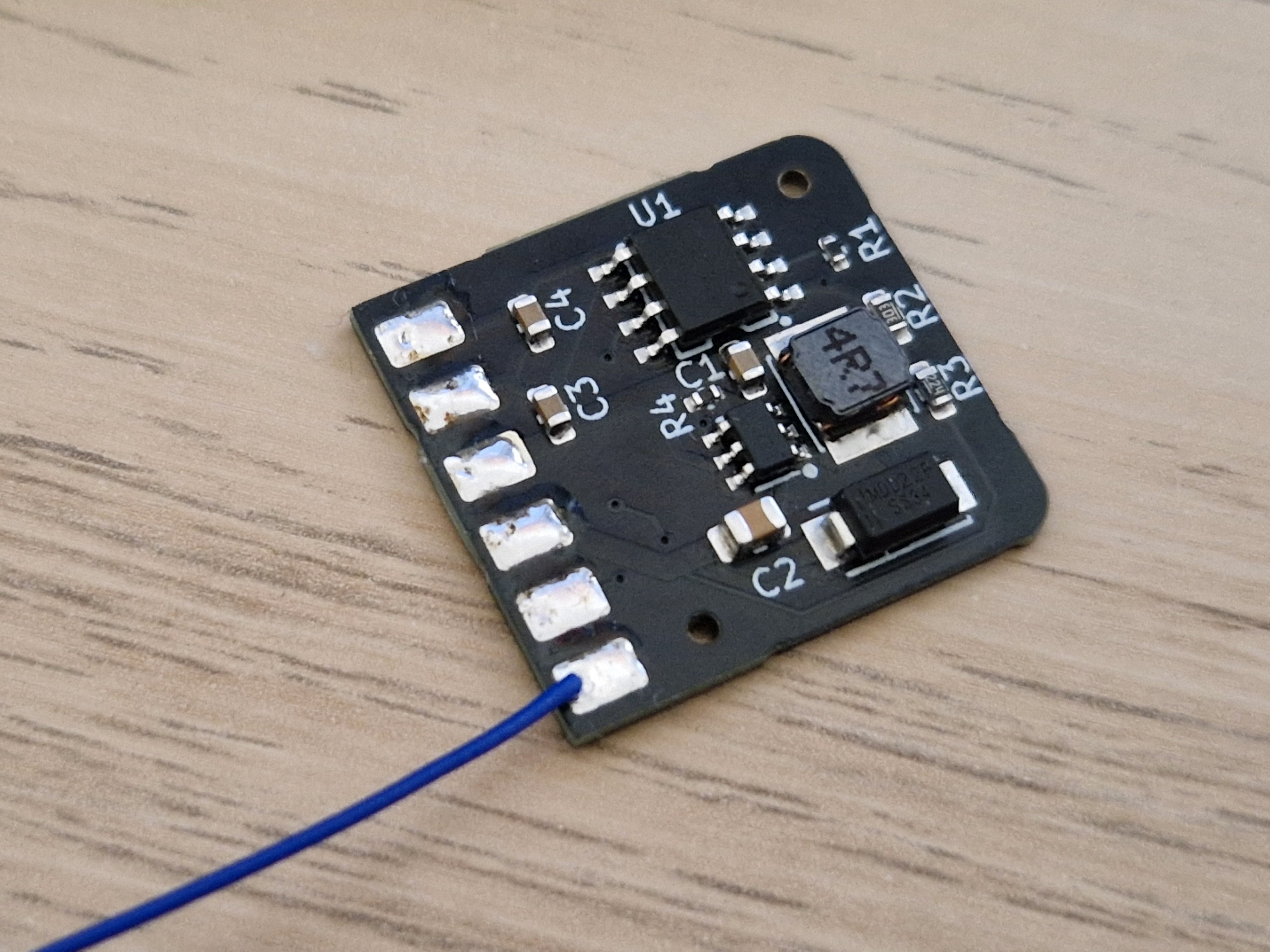
nwpi.kicad_sch - Schematicnwpi.kicad_pcb - PCB layoutproduction/ - Gerbers for JLCPCBvcgencmd get_throttled = 0x0). This also bites after a remote reflash, which powers the Pi off and back on while the calculator is on USB. Fix for the next board revision: a load switch on PI_EN.bad= climbing in nwpi-ctl stat), the dumped headers were FFFF, 0000 or bit-shifted words, and the link worked at ≤ 1.5 MHz but failed at ≥ 2 MHz, all without the calculator being moved. Moving the wires fixed it. Reflow or re-route the MOSI wire (Pi GPIO10 to calculator PA7) if it comes back. To check a link without touching it, lower the clock with echo 2000000 | sudo tee /sys/module/drm_spifb/parameters/spi_hz (0 restores the device tree's 70 MHz): if the errors stop at a lower clock, the wiring is marginal.MIT
| Qty | Value | Footprint | References |
|---|---|---|---|
| 2 | 4.7u | Capacitor_SMD:C_0603_1608Metric | C3, C4 |
| 1 | 10k | Resistor_SMD:R_0402_1005Metric | R4 |
| 1 | 10u | Capacitor_SMD:C_0603_1608Metric | C1 |
| 1 | 220k | Resistor_SMD:R_0603_1608Metric | R3 |
| 1 | 22u | Capacitor_SMD:C_0805_2012Metric | C2 |
| 1 | 2k | Resistor_SMD:R_0402_1005Metric | R1 |
| 1 | 30k | Resistor_SMD:R_0603_1608Metric | R2 |
| 1 | 5V_PI | nwpi:WiredPad_3x2mm | J4 |
| 1 | CHG_STAT | nwpi:WiredPad_3x2mm | J6 |
| 1 | GND | nwpi:WiredPad_3x2mm | J2 |
| 1 | PI_EN | nwpi:WiredPad_3x2mm | J5 |
| 1 | SMNR4020-4R7MT | easyeda2kicad:IND-SMD_L4.0-W4.0_SMNR4020 | L1 |
| 1 | SS34_C8678 | easyeda2kicad:SMA_L4.3-W2.6-LS5.2-RD | D1 |
| 1 | SX1308 | easyeda2kicad:SOT-23-6_L2.9-W1.6-P0.95-LS2.8-BL | U2 |
| 1 | TP4056 | easyeda2kicad:ESOP-8_L4.9-W3.9-P1.27-LS6.0-BL-EP | U1 |
| 1 | VBAT | nwpi:WiredPad_3x2mm | J3 |
| 1 | VUSB | nwpi:WiredPad_3x2mm | J1 |
danielkluka/Diploma-Thesis
Design of a Secure Data Transmission System in NB-IoT Environment

HarryVienna/Slave-clock-controller-with-ESP32-C3-OLED-and-DRV8871
A compact, affordable, and robust controller for analog slave clocks and flip clocks (e.g., Bodet), based on the ESP32-C3 microcontroller and the DRV8871 H-Bridge driver.


waicool20/Divergence-Meter-Project-v2
This is the second iteration of the Divergence Meter Project and another personal learning project, this time learning how to integrate Li-Ion batteries into a project, new electrical converter topologies, Rust…


schwarzschildkugelblitz/The_Hive
Application of Motion tracking and real time data transfer
It measures 20.5 × 19 mm and has 2 copper layers, 1 mm thick.
18 parts, built around the SX1308, TP4056 and SMNR4020-4R7MT. The full list of its parts is on this page, with links to each part's symbol and footprint where PCBKit's library has them.
From the elektricM/nwpi-pcb repository on GitHub, at the commit this page was made from: the board is nwpi.kicad_pcb and its schematic nwpi.kicad_sch. PCBKit opens the board in the browser, with nothing to install.
Its repository publishes it under the CERN-OHL-S-2.0 licence: you may reuse it on that licence's terms (keep the author's notice, and for a copyleft licence share your changes alike).