
2 layers84 × 37.7 mm
Sidebar
Professor-plum/SaintCon-RE-Topper
A reverse engineering themed SaintCon 2024 badge topper
9 parts3MIT

 ElectronicCats/SolderingChallenge2
The classic Soldering challenge
SolderingChallenge is an open-source printed circuit board by ElectronicCats, from the ElectronicCats/SolderingChallenge repository on GitHub, published under the MIT licence. It is a 2-layer board of 16.7 × 14.4 mm with 28 parts on 16 nets, routed with 72 tracks and 8 vias.
It is built around the PY32F002AA15M6TU. Its parts include 4 resistors, 4 diodes, 2 switches, 1 capacitor and 1 IC.
New version 2.0 with Microcontroller PUYA available now!!
This design is based on the work of aspro648 you can support him buying his stuff at Tindie
This design was possible thanks to Mouser electronics, Würth Elektronik and Makers GDL we really appreciate all your support to get this boards free for the Talent Land 2019.
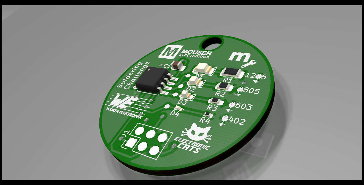 Test your surface mount soldering skills out, starting with a 1206 package and work your way down into the humanly possible solder device, the 0402. Powered by a CR2032 coin cell and Attiny 85 SOIC.
This project is designed using Open Source KiCad. Design files are located in the Hw folder. You can oogle the schematic.
This project is programed using the Open Source Arduino. I use my Open Source AVR Programming Shield to program the Attiny. The firmware is located in the firmware folder.
Aspro648 have posted minimal instructions at HackADay.
Attribution-ShareAlike 3.0 United States (CC BY-SA 3.0 US)
You are free to:
Under the following terms:
| Qty | Value | Footprint | References |
|---|---|---|---|
| 2 | G*** | kibuzzard-67996501 | kibuzzard-67996501, kibuzzard-67996501 |
| 1 | 0.1uF | Capacitor_SMD:C_0805_2012Metric | C1 |
| 1 | 330R | Resistor_SMD:R_0805_2012Metric | R6 |
| 1 | 330R | Resistor_SMD:R_1206_3216Metric_Pad1.30x1.75mm_HandSolder | R5 |
| 1 | 330R | Resistor_SMD:R_0402_1005Metric_Pad0.72x0.64mm_HandSolder | R9 |
| 1 | 330R | Resistor_SMD:R_0603_1608Metric_Pad0.98x0.95mm_HandSolder | R7 |
| 1 | Battery_Cell | solderingChallenge:BAT-HLD-001 | BT1 |
| 1 | Blue | LED_SMD:LED_0603_1608Metric_Pad1.05x0.95mm_HandSolder | D7 |
| 1 | G*** | kibuzzard-6797B453 | kibuzzard-6797B453 |
| 1 | G*** | kibuzzard-67914E01 | kibuzzard-67914E01 |
| 1 | G*** | kibuzzard-67914DBF | kibuzzard-67914DBF |
| 1 | G*** | kibuzzard-67914DE9 | kibuzzard-67914DE9 |
| 1 | G*** | kibuzzard-679163A9 | kibuzzard-679163A9 |
| 1 | G*** | kibuzzard-67916B62 | kibuzzard-67916B62 |
| 1 | G*** | kibuzzard-679168F3 | kibuzzard-679168F3 |
| 1 | G*** | kibuzzard-67916383 | kibuzzard-67916383 |
| 1 | G*** | kibuzzard-679163CD | kibuzzard-679163CD |
| 1 | G*** | kibuzzard-67914DD8 | kibuzzard-67914DD8 |
| 1 | G*** | kibuzzard-679168C7 | kibuzzard-679168C7 |
| 1 | Green | LED_SMD:LED_1206_3216Metric_Pad1.42x1.75mm_HandSolder | D5 |
| 1 | LOGO | Aesthetics:electronic_cats_logo_4x3 | G*** |
| 1 | On | solderingChallenge:MSK12C02 | SW2 |
| 1 | PY32F002AA15M6TU | solderingChallenge:PY32F002AA15M | U1 |
| 1 | Red | LED_SMD:LED_0805_2012Metric | D6 |
| 1 | SWD | Connector_PinHeader_2.54mm:PinHeader_1x04_P2.54mm_Vertical | J2 |
| 1 | SW_RST | Button_Switch_SMD:SW_SPST_TL3342 | SW1 |
| 1 | Yellow | LED_SMD:LED_0402_1005Metric_Pad0.77x0.64mm_HandSolder | D9 |
Professor-plum/SaintCon-RE-Topper
A reverse engineering themed SaintCon 2024 badge topper

michpro/PY32F002_ESSOP10_minimal_board
Puya PY32F002A ARM M0+ minimal development board (ESSOP10 package)

ElectronicCats/BADGE-MALWARE-SPACE-2025
Prerequisites: You must have the Arm GNU Toolchain ( ) installed on your system.


It measures 16.7 × 14.4 mm and has 2 copper layers, 1.6 mm thick.
28 parts, built around the PY32F002AA15M6TU. The full list of its parts is on this page, with links to each part's symbol and footprint where PCBKit's library has them.
From the ElectronicCats/SolderingChallenge repository on GitHub, at the commit this page was made from: the board is Hw/solderingChallenge.kicad_pcb and its schematic Hw/solderingChallenge.kicad_sch. PCBKit opens the board in the browser, with nothing to install.
Its repository publishes it under the MIT licence: you may reuse it on that licence's terms (keep the author's notice, and for a copyleft licence share your changes alike).