

2 layers16.7 × 14.4 mm

A reverse engineering themed SaintCon 2024 badge topper
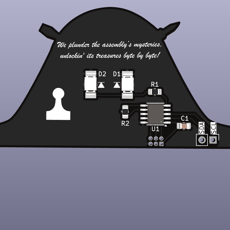
Sidebar is an open-source printed circuit board by Professor-plum, from the Professor-plum/SaintCon-RE-Topper repository on GitHub, published under the MIT licence. It is a 2-layer board of 84 × 37.7 mm with 9 parts on 12 nets, routed with 37 tracks and 1 via.
It is built around the PY32F002AA15M6TU. Its parts include 3 connectors, 2 resistors, 2 diodes, 1 capacitor and 1 IC.
A reverse engineering themed SaintCon 2024 badge topper

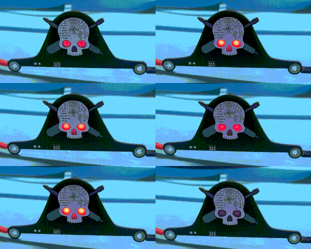
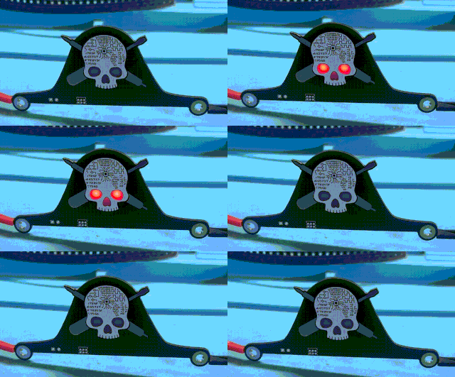
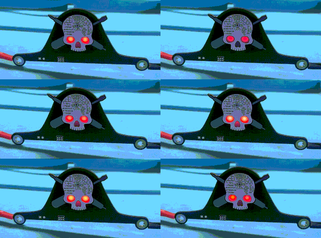
This topper can blink the LEDs in one of four patterns that can be selected by touching the skull (captive touch)

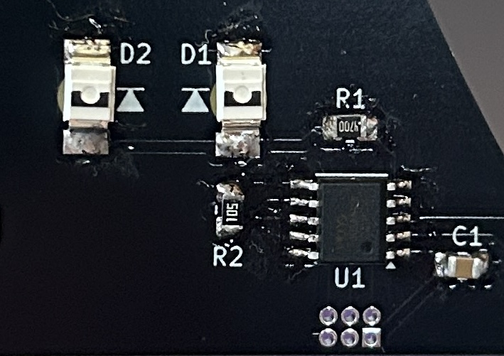
[!NOTE] If you obtained the components during Saintcon the py32 is already flashed and you can skip the remainder of these steps.
Required hardware & software
Connect 3.3V, GND, SWDIO, SWCLK, and RST to the ST-Link. These are all broken out on the 2x3 1.00mm pin header.
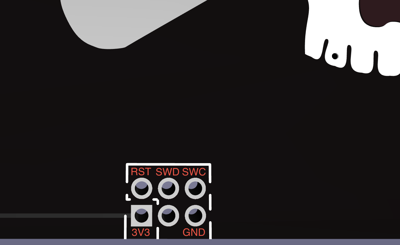
To flash the MCU just execute make flash from the Fimware directory.
| Qty | Value | Footprint | References |
|---|---|---|---|
| 2 | LED | Grange:Reverse_LED | D1, D2 |
| 1 | 1M | Resistor_SMD:R_0805_2012Metric_Pad1.20x1.40mm_HandSolder | R2 |
| 1 | C | Capacitor_SMD:C_0805_2012Metric_Pad1.18x1.45mm_HandSolder | C1 |
| 1 | Conn_01x02_Pin | Connector_PinHeader_2.54mm:PinHeader_1x02_P2.54mm_Vertical | J3 |
| 1 | Conn_02x03_Odd_Even | Connector_PinHeader_1.27mm:PinHeader_2x03_P1.27mm_Vertical | J1 |
| 1 | PY32F002AA15M | Grange:SSOP-10_3.9x4.9mm_P1.00mm | U1 |
| 1 | R_US | Resistor_SMD:R_0805_2012Metric_Pad1.20x1.40mm_HandSolder | R1 |
| 1 | Screw_Power | Saintcon2024Klip-ons:Saintcon2024Klip-onUpper | J2 |

michpro/PY32F002_ESSOP10_minimal_board
Puya PY32F002A ARM M0+ minimal development board (ESSOP10 package)

ElectronicCats/BADGE-MALWARE-SPACE-2025
Prerequisites: You must have the Arm GNU Toolchain ( ) installed on your system.


It measures 84 × 37.7 mm and has 2 copper layers, 1.6 mm thick.
9 parts, built around the PY32F002AA15M6TU. The full list of its parts is on this page, with links to each part's symbol and footprint where PCBKit's library has them.
From the Professor-plum/SaintCon-RE-Topper repository on GitHub, at the commit this page was made from: the board is Kicad/Sidebar.kicad_pcb and its schematic Kicad/Sidebar.kicad_sch. PCBKit opens the board in the browser, with nothing to install.
Its repository publishes it under the MIT licence: you may reuse it on that licence's terms (keep the author's notice, and for a copyleft licence share your changes alike).