2 layers111.1 × 86 mm
TeensyOpenLoop
neurorishika/MultiBiOS
High-precision, hardware-clocked olfactometer control system for behavioral neuroscience
25 partsMIT

 ekatynski/WCS1700-Calibrator
A board designed to aid in calibrating six Winson WCS1700 hall effect sensors a the same time.
WCS1700-Calibrator is an open-source printed circuit board by ekatynski, from the ekatynski/WCS1700-Calibrator repository on GitHub. It is a 4-layer board of 79.6 × 92.5 mm with 120 parts on 139 nets, routed with 603 tracks and 558 vias.
It is built around the TEENSY 4.1, MCP3208-BI/P and TLP241A(TP1,F, with the LT1962EMS8-5#TRPBF, TXB0106PW and AO3422 among its other parts. Its parts include 31 capacitors, 28 ICs, 26 resistors, 11 connectors and 5 transistors. It belongs with the NXP (LPC, Kinetis, i.MX RT) boards of this library.


View this project on CADLAB.io.
A board designed to aid in calibrating six Winson WCS1700 hall effect sensors at the same time as well as the software needed to drive it.
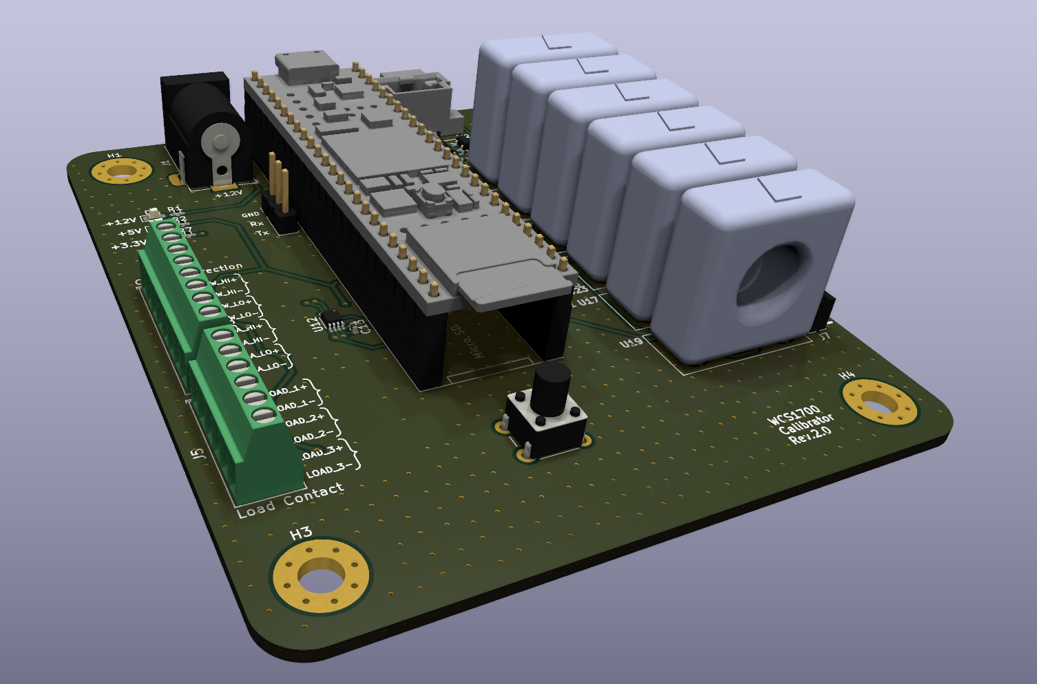
Schematic and BOM can both be found in the /hardware/ section of this repository. Expanded description of hardware functionality coming soon.
All software can be found in the /software/ section of this repository. Expanded description of software functionality coming soon. In addition, software updates to expand contactor control functionality and independent current volume is on the way, but the software necessary to simply monitor and report the WCS1700 hall effect sensor outputs is ready and implemented.
An assembly guide for this board can be found in this repository at /hardware/bom/
The hardware of this project has advanced to support contactor control via relay connections. Four of these contactors form a would-be H-bridge to control load current flow direction while the remaining three allow current flow across individual load resistors to increase or decrease current volume. The hardware has also advanced to support independent current monitoring via a Tamura L01Z series hall effect sensor. The software to drive these features is not yet in place. The following is a list of development items not yet complete:
U4| Qty | Value | Footprint | References |
|---|---|---|---|
| 24 | 0.1uF 25V | Capacitor_SMD:C_0402_1005Metric_Pad0.74x0.62mm_HandSolder | C1, C2, C10, C11, C12, C13, C14, C15, C16, C17, C18, C19, C20, C21, C22, C23 +8 |
| 14 | 4.7K | Resistor_SMD:R_0402_1005Metric_Pad0.72x0.64mm_HandSolder | R1, R2, R7, R8, R9, R14, R15, R16, R17, R18, R19, R20, R21, R26 |
| 7 | 500R | Resistor_SMD:R_0402_1005Metric_Pad0.72x0.64mm_HandSolder | R10, R11, R12, R13, R22, R23, R24 |
| 7 | TLP241A(TP1,F | OptoDevice:OnSemi_CASE100CY | U7, U8, U9, U10, U14, U15, U16 |
| 6 | ADR02AUJZ | Package_TO_SOT_SMD:SOT-23-5_HandSoldering | U18, U20, U22, U24, U26, U28 |
| 6 | Conn_01x03_Socket | Connector_PinSocket_1.27mm:PinSocket_1x03_P1.27mm_Vertical | J6, J7, J8, J9, J10, J11 |
| 6 | TestPoint | TestPoint:TestPoint_Pad_D1.0mm | TP1, TP2, TP3, TP4, TP5, TP6 |
| 6 | WCS1700 | Sensor_Hall_Effect:WCS1700 | U17, U19, U21, U23, U25, U27 |
| 5 | 1uF 25V | Capacitor_SMD:C_0402_1005Metric_Pad0.74x0.62mm_HandSolder | C3, C4, C5, C8, C9 |
| 5 | AO3422 | Package_TO_SOT_SMD:SOT-23 | Q1, Q2, Q3, Q4, Q5 |
| 4 | 2.2K 0.1% | Resistor_SMD:R_0402_1005Metric_Pad0.72x0.64mm_HandSolder | R3, R4, R5, R6 |
| 4 | MountingHole | MountingHole:MountingHole_4mm_Pad_Via | H1, H2, H3, H4 |
| 3 | 150060VS75000 | LED_SMD:LED_0603_1608Metric_Pad1.05x0.95mm_HandSolder | D1, D3, D4 |
| 3 | Jumper_2_Open | Jumper:SolderJumper-2_P1.3mm_Open_TrianglePad1.0x1.5mm | JP1, JP2, JP3 |
| 2 | MAX6107 | Package_TO_SOT_SMD:SOT-23 | U1, U2 |
| 2 | MCP3208 | Package_SO:SOIC-16_3.9x9.9mm_P1.27mm | U4, U5 |
| 1 | 0.01uF 10V | Capacitor_SMD:C_0402_1005Metric_Pad0.74x0.62mm_HandSolder | C6 |
| 1 | 0ZCJ0050AF2E | Fuse:Fuse_1206_3216Metric_Pad1.42x1.75mm_HandSolder | TH1 |
| 1 | 10K | Resistor_SMD:R_0402_1005Metric_Pad0.72x0.64mm_HandSolder | R25 |
| 1 | 10uF 10V | Capacitor_SMD:C_0402_1005Metric_Pad0.74x0.62mm_HandSolder | C7 |
| 1 | 282834-6 | TerminalBlock_TE-Connectivity:TerminalBlock_TE_282834-6_1x06_P2.54mm_Horizontal | J5 |
| 1 | 282834-8 | TerminalBlock_TE-Connectivity:TerminalBlock_TE_282834-8_1x08_P2.54mm_Horizontal | J3 |
| 1 | 560020-0330 | connector:CONN_560020-0330_MOL | J2 |
| 1 | 74LVC2G240DC,125 | Package_SO:VSSOP-8_2.3x2mm_P0.5mm | U12 |
| 1 | B0520LW-7-F | Diode_SMD:D_SOD-123 | D2 |
| 1 | Conn_01x03_Pin | Connector_PinHeader_2.54mm:PinHeader_1x03_P2.54mm_Vertical | J4 |
| 1 | LT1962EMS8-5#TRPBF | Package_SO:MSOP-8_3x3mm_P0.65mm | U3 |
| 1 | PJ-002B | Connector_BarrelJack:BarrelJack_Horizontal | J1 |
| 1 | SN74AUC2G08DCUR | Package_SO:VSSOP-8_2.3x2mm_P0.5mm | U11 |
| 1 | TXB0106PW | Package_SO:TSSOP-16_4.4x5mm_P0.65mm | U6 |
| 1 | Teensy4.1 | teensy:Teensy41 | U13 |
| 1 | 1825910-6 | Button_Switch_THT:SW_PUSH_6mm_H8mm | SW1 |
neurorishika/MultiBiOS
High-precision, hardware-clocked olfactometer control system for behavioral neuroscience


ekatynski/Test-Stand-Power-Monitor
A small board for cheaply and easily monitoring a motor test stand for a host of data types.


openhwfoundation/core-v-mcu-devkit
This is the CORE-V MCU DevKit project, hosting the open-source artifacts for the CORE-V MCU Development Kit.


FranTerrassa/Ardutester
Aparato a base de arduino para comprobar estado de componentes electrónicos

luispaulomr/alr3000z_firmware
Firmware for ALR3000z (development board based on PIC18F4550).
It measures 79.6 × 92.5 mm and has 4 copper layers, 1.6 mm thick.
120 parts, built around the TEENSY 4.1, MCP3208-BI/P, TLP241A(TP1,F and LT1962EMS8-5#TRPBF. The full list of its parts is on this page, with links to each part's symbol and footprint where PCBKit's library has them.
From the ekatynski/WCS1700-Calibrator repository on GitHub, at the commit this page was made from: the board is hardware/WCS1700_Calibrator.kicad_pcb and its schematic hardware/ADC_and_level_shift.kicad_sch. PCBKit opens the board in the browser, with nothing to install.
Its repository states no licence, so its author keeps all rights: ask ekatynski before reusing the design.