4 layers65 × 56 mm

 eiten/canbus_laser_toolhead
CANbus Laser Toolhed PCB
Laser CANbus Toolhead is an open-source printed circuit board by eiten, from the eiten/canbus_laser_toolhead repository on GitHub. It is a 4-layer board of 50 × 30 mm with 84 parts on 67 nets, routed with 212 tracks and 136 vias.
It is built around the 74AHCT1G125SE, SN65HVD230D and ICM-20602, with the MP2459GJ, XC6206P332MR-G and 1N5819WS among its other parts. Its parts include 24 capacitors, 20 resistors, 10 diodes, 6 ICs and 2 transistors. It belongs with the interfaces and adapters boards and the STM32 boards of this library.


A compact, robust toolhead board for Klipper-based laser engravers and cutters (CoreXY). This board integrates power supply, laser driver logic, CAN-Bus communication, and input shaping (ICM-20602) in the smallest possible space.
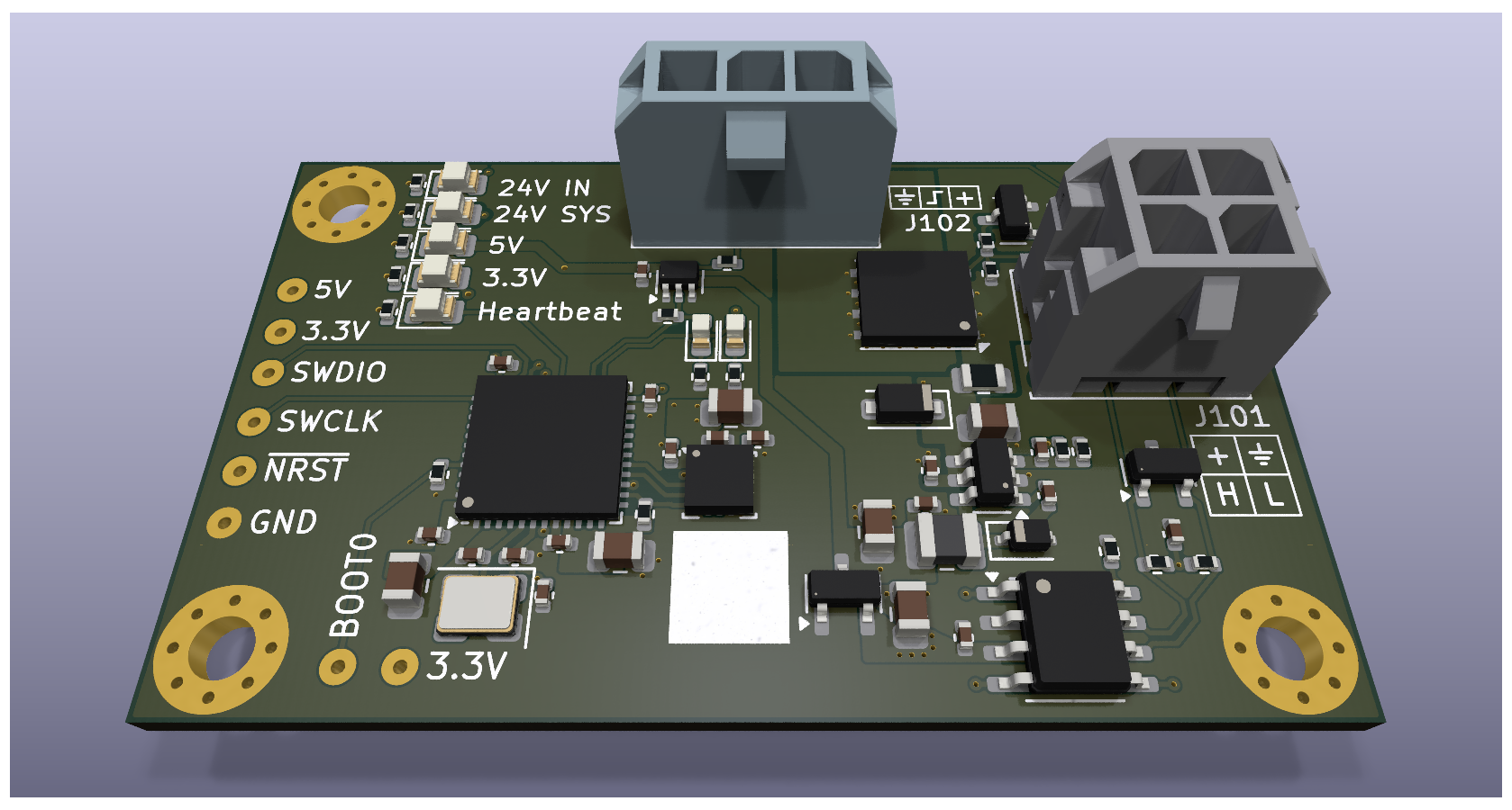
[mcu toolhead]
canbus_uuid: <your-uuid>  # Find with "ls /dev/serial/by-id/*" or "~/klippy-env/bin/python ~/klipper/scripts/canbus_query.py can0"

[temperature_sensor toolhead_mcu]
sensor_type: temperature_mcu
sensor_mcu: toolhead[mpu9250]
cs_pin: toolhead:PA4
spi_bus: spi1
#axes_map: x,y,z # Configure according to your printer orientation
[resonance_tester]
accel_chip: mpu9250
probe_points:
150, 150, 20 # Adjust to your bed size# Laser PWM Signal
[output_pin laser_pwm]
pin: toolhead:PB14
pwm: True
cycle_time: 0.001 # 1kHz PWM frequency
shutdown_value: 0 # Safety: laser off during emergency
# Laser Enable (optional)
[output_pin laser_enable]
pin: toolhead:PB15
value: 0
shutdown_value: 0
# Heartbeat LED (optional)
[output_pin heartbeat]
pin: toolhead:PA9
pwm: True
cycle_time: 1.0| Pin | Signal | Description |
|---|---|---|
| 1 | +24V | Main power input (High Current) |
| 2 | GND | Ground |
| 3 | CAN_H | CAN-Bus High Signal |
| 4 | CAN_L | CAN-Bus Low Signal |
| Pin | Signal | Description |
|---|---|---|
| 1 | GND | Laser Ground |
| 2 | PWM | 5V PWM Signal (Level-Shifted) |
| 3 | +24V | Switched Laser Power (Soft-Start) |
| Pad | Pin | Signal | Function |
|---|---|---|---|
| 1 | - | 5V | 5V Supply (from Programmer) |
| 2 | - | 3.3V | VTref (Reference Voltage) |
| 3 | PA13 | SWDIO | Serial Wire Debug I/O |
| 4 | PA14 | SWCLK | Serial Wire Debug Clock |
| 5 | - | NRST | Reset Signal |
| 6 | - | GND | Ground |
💡 Bootloader Mode: To force the STM32 into DFU/Bootloader mode (e.g., for initial flash with Katapult), bridge the BOOT0 pad with 3.3V during power-on.
make flash FLASH_DEVICE=<dfu-device>~/klippy-env/bin/python ~/klipper/scripts/canbus_query.py can0| Component | Value/Type | Function | Package | Order Code |
|---|---|---|---|---|
| U101 | STM32F072CBU6 | Main Microcontroller | UFQFPN-48 | STM32F072CBU6 |
| U102 | MP2459GJ-Z | Buck Converter 24V→5V | TSOT-23-8 | MP2459GJ-Z |
| U105 | SN65HVD230DR | CAN-Bus Transceiver | SOIC-8 | SN65HVD230DR |
| U106 | ICM-20602 | 6-Axis IMU (Accelerometer/Gyroscope) | LGA-16 | ICM-20602 |
| Q101 | CJAC70P06 | P-MOSFET (Laser Switch, 60V) | SOIC-8 | CJAC70P06 |
| D101 | SMF24A | TVS Diode (Overvoltage Protection) | DO-214AC | SMF24A |
| F101 | 1812L025 | PTC Fuse 250mA | 1812 | 1812L025 |
| Y101 | 12MHz | Crystal for CAN Stability | HC-49/S | 12MHz Crystal |
| J101/J102 | Micro-Fit 3.0 | THT Connectors | THT | Micro-Fit 3.0 THT |
| Parameter | Value | Unit |
|---|---|---|
| Input Voltage | 24 ± 2 | V |
| Laser Current (max) | 4 | A |
| CAN Baud Rate | 1 | Mbit/s |
| PWM Frequency | 1 | kHz |
| Soft-Start Time | ~1.2 | ms |
| Operating Temperature | -10 to +70 | °C |
| Dimensions | TBD | mm |
This project is licensed under the Creative Commons Attribution-NonCommercial-ShareAlike 4.0 International License (CC BY-NC-SA 4.0).

This means you are free to:
Under the following terms:
For the full license text, visit: https://creativecommons.org/licenses/by-nc-sa/4.0/
Note: The original documentation is in German (README.de.md). This English version is a translation for international users.
| Qty | Value | Footprint | References |
|---|---|---|---|
| 14 | 100n | Capacitor_SMD:C_0402_1005Metric | C104, C105, C106, C107, C108, C109, C111, C113, C114, C117, C118, C120, C122, C123 |
| 6 | 10k | Resistor_SMD:R_0402_1005Metric | R101, R103, R107, R108, R112, R113 |
| 5 | 10u | Capacitor_SMD:C_0805_2012Metric | C103, C110, C116, C121, C124 |
| 4 | MountingHole | MountingHole:MountingHole_2.7mm_Pad_Via | H101, H102, H103, H104 |
| 4 | green | LED_SMD:LED_0805_2012Metric | D104, D105, D106, D107 |
| 3 | 100k | Resistor_SMD:R_0402_1005Metric | R104, R105, R106 |
| 3 | 33p | Capacitor_SMD:C_0402_1005Metric | C101, C102, C115 |
| 2 | 1k | Resistor_SMD:R_0402_1005Metric | R109, R118 |
| 2 | 3.3V | prj:NAMED_TEST_POINT | TP102, TP108 |
| 2 | 33k | Resistor_SMD:R_0402_1005Metric | R114, R115 |
| 2 | 470R | Resistor_SMD:R_0402_1005Metric | R119, R120 |
| 2 | 60R4 | Resistor_SMD:R_0402_1005Metric | R110, R111 |
| 2 | red | LED_SMD:LED_0603_1608Metric | D109, D110 |
| 1 | /BOOT0 | prj:NAMED_TEST_POINT | TP107 |
| 1 | /SWCLK | prj:NAMED_TEST_POINT | TP106 |
| 1 | /SWDIO | prj:NAMED_TEST_POINT | TP105 |
| 1 | /~{NRST} | prj:NAMED_TEST_POINT | TP104 |
| 1 | 12 MHz | Crystal:Crystal_SMD_3225-4Pin_3.2x2.5mm | Y101 |
| 1 | 1N5819WS | Diode_SMD:D_SOD-323 | D102 |
| 1 | 220R | Resistor_SMD:R_0402_1005Metric | R117 |
| 1 | 22u | Capacitor_SMD:C_0805_2012Metric | C112 |
| 1 | 250mA | Fuse:Fuse_0805_2012Metric | F101 |
| 1 | 2N7002 | Package_TO_SOT_SMD:SOT-23 | Q102 |
| 1 | 3.3k | Resistor_SMD:R_0402_1005Metric | R116 |
| 1 | 4n7 | Capacitor_SMD:C_0402_1005Metric | C119 |
| 1 | 51k | Resistor_SMD:R_0402_1005Metric | R102 |
| 1 | 5V | prj:NAMED_TEST_POINT | TP101 |
| 1 | 74AHCT1G125 | Package_TO_SOT_SMD:SOT-353_SC-70-5 | U104 |
| 1 | CJAC70P06 | Package_DFN_QFN:AO_DFN-8-1EP_5.55x5.2mm_P1.27mm_EP4.12x4.6mm | Q103 |
| 1 | CREATED BY | prj:EduardIten | LABEL101 |
| 1 | GND | prj:NAMED_TEST_POINT | TP103 |
| 1 | ICM-20602 | Package_LGA:LGA-16_3x3mm_P0.5mm_LayoutBorder3x5y | U107 |
| 1 | In | Connector_Molex:Molex_Micro-Fit_3.0_43045-0412_2x02_P3.00mm_Vertical | J101 |
| 1 | L | Inductor_SMD:L_1008_2520Metric | L101 |
| 1 | LICENSE | prj:CC_BY_NC_SA 4 | LABEL103 |
| 1 | Laser | Connector_Molex:Molex_Micro-Fit_3.0_43650-0315_1x03_P3.00mm_Vertical | J102 |
| 1 | MP2459 | Package_TO_SOT_SMD:SOT-23-6 | U102 |
| 1 | PCB NAME | prj:CLT Rev. xxx | LABEL102 |
| 1 | PESD1CAN | Package_TO_SOT_SMD:SOT-23 | D103 |
| 1 | SERIAL | prj:SERIAL_No | LABEL104 |
| 1 | SMF24A | Diode_SMD:D_SOD-123F | D101 |
| 1 | SN65HVD230 | Package_SO:SOIC-8_3.9x4.9mm_P1.27mm | U105 |
| 1 | STM32F072CBUx | Package_DFN_QFN:QFN-48-1EP_7x7mm_P0.5mm_EP5.6x5.6mm | U101 |
| 1 | Term | Jumper:SolderJumper-2_P1.3mm_Bridged_RoundedPad1.0x1.5mm | JP101 |
| 1 | XC6206P332MR-G | Package_TO_SOT_SMD:SOT-23-3 | U103 |
| 1 | yellow | LED_SMD:LED_0805_2012Metric | D108 |
It measures 50 × 30 mm and has 4 copper layers, 1.6 mm thick.
84 parts, built around the 74AHCT1G125SE, SN65HVD230D, ICM-20602 and MP2459GJ. The full list of its parts is on this page, with links to each part's symbol and footprint where PCBKit's library has them.
From the eiten/canbus_laser_toolhead repository on GitHub, at the commit this page was made from: the board is Laser CANbus Toolhead.kicad_pcb and its schematic Laser CANbus Toolhead.kicad_sch. PCBKit opens the board in the browser, with nothing to install.
Its repository states no licence, so its author keeps all rights: ask eiten before reusing the design.

Talw3g/linear_act_controller
Controller for 24V linear actuator with potentiometer position control and feedback.

Seeed-Studio/OSHW-reCamera-Series
reCamera is a series of open-source AI cameras.


florolf/lab-automation
Plugs into relay and can be used to provide switchable 5V USB power to downstream devices.

fulgidus/hardware
Learning KiCad takes time, and pollutes with weird and incomplete projects. Here they are...