4 layers50 × 30 mm

 eiten/EWS1
Universal 3D-Printer HAT for SBC with CAN-Interface and USB Hub
EWS is an open-source printed circuit board by eiten, from the eiten/EWS repository on GitHub. It is a 4-layer board of 65 × 56 mm with 124 parts on 142 nets, routed with 433 tracks and 566 vias.
It is built around the XR76208EL-F, USBLC6-2SC6 and TPS2557DRB, with the CH334F, TJA1051TK/3/1 and XC6206P332MR among its other parts. Its parts include 30 capacitors, 29 resistors, 12 diodes, 10 ICs and 7 connectors. It belongs with the interfaces and adapters and robots and motor control boards and the STM32 boards of this library.


A universal interface board (HAT) for Raspberry Pi 4/5 and Radxa Rock 5B designed for use in Voron 3D printers. Provides powerful 5V supply (8A), CAN-Bus interface (USB-Bridge or Native), and USB hub.
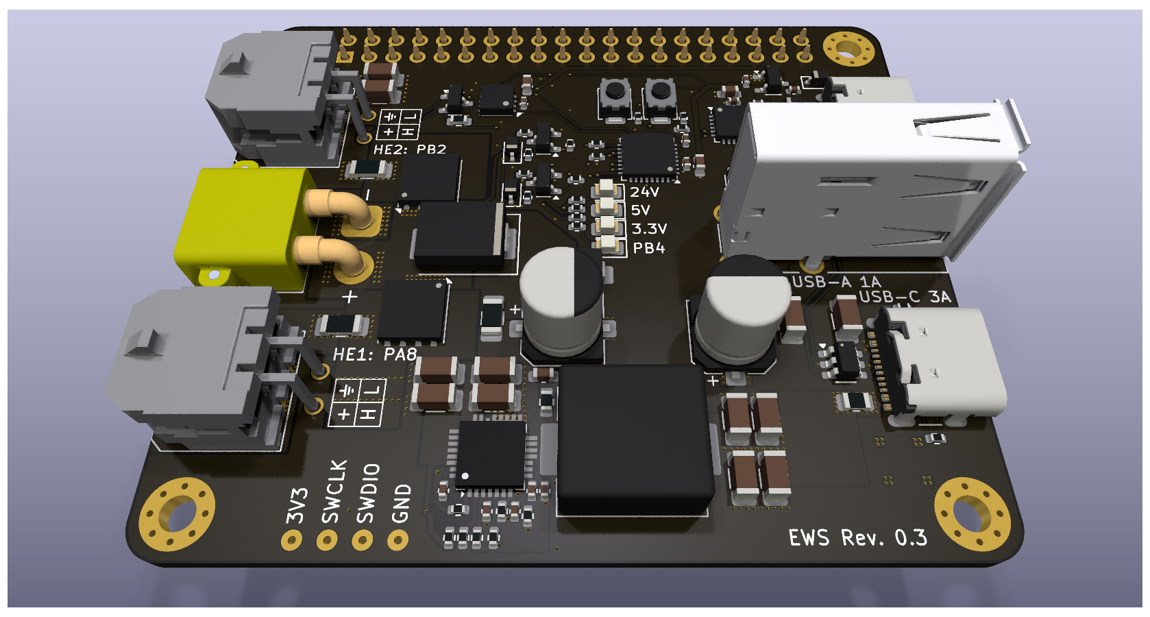
EWS stands for "Eierlegende Wollmilchsau" (German for "egg-laying woolly milk pig") - a humorous term for a universal solution that does everything. This HAT lives up to its nickname by combining multiple essential functions for Voron 3D printer control systems in a single, compact board.
The board addresses common pain points in Voron builds by providing robust power distribution, reliable CAN communication, and convenient USB connectivity while maintaining compatibility with both Raspberry Pi and Radxa Rock 5B single-board computers.
This board was designed to solve multiple critical issues commonly encountered in high-performance 3D printer setups:
USB Port Protection:
[mcu hat]
canbus_uuid: your_uuid_here
# Alternative for USB connection:
# serial: /dev/serial/by-id/usb-katapult_stm32g0b1xx_your_id-if00

[temperature_sensor hat_mcu]
sensor_type: temperature_mcu
sensor_mcu: hat| Parameter | Specification |
|---|---|
| Form Factor | Standard HAT (65mm x 56mm) |
| Layer Stack | 4-Layer Multilayer |
| Layer 1 (Top) | Signal/Power |
| Layer 2 | GND Plane |
| Layer 3 | 5V Power Plane |
| Layer 4 (Bottom) | Signal/GND |
| Solder Mask | Black Matte |
| Surface Finish | ENIG (Gold) |
| Silkscreen | White |
| Mounting | Inner mounting holes (Pi/Rock compatible) |
| EMI Design | Mounting holes via-stitched to GND planes (Layer 2 & Bottom), isolated from 5V plane (Layer 3) |
| Parameter | Value | Unit |
|---|---|---|
| Input Voltage | 24 ± 2 | V |
| 5V Output Current | 8 | A |
| Logic Supply Current | 2 | A |
| CAN Baud Rate | up to 1 | Mbit/s |
| USB Speed | 480 | Mbit/s |
| Operating Temperature | -10 to +70 | °C |
| Dimensions | 65 x 56 | mm |
For detailed information about changes and updates, see CHANGELOG.md.
This project is licensed under the Creative Commons Attribution-NonCommercial-ShareAlike 4.0 International License (CC BY-NC-SA 4.0).

This means you are free to:
Under the following terms:
For the full license text, visit: https://creativecommons.org/licenses/by-nc-sa/4.0/
Note: The original documentation is in German (README.de.md). This English version is a translation for international users.
| Qty | Value | Footprint | References |
|---|---|---|---|
| 8 | 22u | Capacitor_SMD:C_1206_3216Metric | C214, C215, C216, C217, C306, C307, C405, C406 |
| 8 | 33k | Resistor_SMD:R_0402_1005Metric | R207, R401, R402, R403, R404, R405, R406, R413 |
| 7 | 100n | Capacitor_SMD:C_0402_1005Metric | C208, C210, C301, C302, C305, C401, C404 |
| 5 | 10k | Resistor_SMD:R_0402_1005Metric | R204, R206, R303, R411, R412 |
| 5 | 1k | Resistor_SMD:R_0402_1005Metric | R203, R302, R305, R407, R408 |
| 5 | ~ | Jumper:SolderJumper-2_P1.3mm_Open_RoundedPad1.0x1.5mm | JP303, JP304, JP305, JP306, JP307 |
| 4 | 10u | Capacitor_SMD:C_1206_3216Metric | C202, C204, C205, C206 |
| 4 | MountingHole_Pad | MountingHole:MountingHole_2.7mm_Pad_Via | MH101, MH102, MH103, MH104 |
| 4 | ~ | project:SolderJumper-3_P1.3mm_Bridged12_RoundedPad1.0x1.5mm_custom | JP301, JP302, JP401, JP402 |
| 3 | 10u | Capacitor_SMD:C_0603_1608Metric | C303, C304, C402 |
| 3 | 1u | Capacitor_SMD:C_0402_1005Metric | C203, C207, C211 |
| 3 | 5k1 | Resistor_SMD:R_0402_1005Metric | R208, R409, R410 |
| 3 | USBLC6-2SC6 | Package_TO_SOT_SMD:SOT-23-6 | U402, U403, U404 |
| 3 | YELLOW | LED_SMD:LED_0805_2012Metric | D201, D202, D203 |
| 2 | 100u | Capacitor_SMD:CP_Elec_6.3x7.7 | C201, C403 |
| 2 | 1N5819WS | Diode_SMD:D_SOD-323 | D405, D406 |
| 2 | 5A | Fuse:Fuse_1206_3216Metric_Pad1.42x1.75mm_HandSolder | F401, F402 |
| 2 | AO3400A | Package_TO_SOT_SMD:SOT-23 | Q403, Q404 |
| 2 | BZT52C15S | Diode_SMD:D_SOD-323 | D401, D402 |
| 2 | CJAC70P06 | Package_DFN_QFN:AO_DFN-8-1EP_5.55x5.2mm_P1.27mm_EP4.12x4.6mm | Q401, Q402 |
| 2 | MX3.0 2x2 | Connector_Molex:Molex_Micro-Fit_3.0_43045-0400_2x02_P3.00mm_Horizontal | J402, J403 |
| 2 | TPS2557 | project:S-PVSON-N8 | U405, U406 |
| 2 | TS-1088 | Button_Switch_SMD:SW_SPST_TS-1088-xR020 | SW301, SW302 |
| 2 | USB-C | Connector_USB:USB_C_Receptacle_GCT_USB4105-xx-A_16P_TopMnt_Horizontal | J404, J405 |
| 1 | 120R | Resistor_SMD:R_0603_1608Metric | R304 |
| 1 | 15k | Resistor_SMD:R_0402_1005Metric | R210 |
| 1 | 1R | Resistor_SMD:R_0603_1608Metric | R209 |
| 1 | 1n | Capacitor_SMD:C_0402_1005Metric | C213 |
| 1 | 220p | Capacitor_SMD:C_0603_1608Metric | C212 |
| 1 | 22k | Resistor_SMD:R_0402_1005Metric | R201 |
| 1 | 2k | Resistor_SMD:R_0402_1005Metric | R211 |
| 1 | 2k2 | Resistor_SMD:R_0402_1005Metric | R202 |
| 1 | 3.3uH | Inductor_SMD:L_APV_APH1050 | L201 |
| 1 | 330R | Resistor_SMD:R_0402_1005Metric | R301 |
| 1 | 3A | Fuse:Fuse_1206_3216Metric_Pad1.42x1.75mm_HandSolder | F201 |
| 1 | 3V3 | project:NAMED_TEST_POINT | TP201 |
| 1 | 4u7 | Capacitor_SMD:C_0402_1005Metric | C209 |
| 1 | 5V | TestPoint:TestPoint_Pad_D3.0mm | TP202 |
| 1 | 68k | Resistor_SMD:R_0603_1608Metric | R414 |
| 1 | BZT52C4V7 | Diode_SMD:D_SOD-123 | D204 |
| 1 | CH334F | Package_DFN_QFN:QFN-24-1EP_4x4mm_P0.5mm_EP2.7x2.7mm_ThermalVias | U401 |
| 1 | CREATED BY | project:EduardIten | LABEL102 |
| 1 | GND | TestPoint:TestPoint_Pad_D3.0mm | TP203 |
| 1 | GND | project:NAMED_TEST_POINT | TP301 |
| 1 | GPIO | Connector_PinSocket_2.54mm:PinSocket_2x20_P2.54mm_Vertical | J301 |
| 1 | GREEN | LED_SMD:LED_0805_2012Metric | D301 |
| 1 | Heatsink | project:HeatSink_9x9x5 | HS201 |
| 1 | LICENSE | project:CC_BY_NC_SA 4 | LABEL104 |
| 1 | NetTie_2 | NetTie:NetTie-2_SMD_Pad0.5mm | NT201 |
| 1 | PCB NAME | project:EWS Rev. 1.0 | LABEL101 |
| 1 | PESD1CAN | Package_TO_SOT_SMD:SOT-23 | D302 |
| 1 | SMAJ26A | Diode_SMD:D_SMA | D404 |
| 1 | SS56 | Diode_SMD:D_SMC | D403 |
| 1 | STM32G0B1KBUx | Package_DFN_QFN:QFN-32-1EP_5x5mm_P0.5mm_EP3.45x3.45mm | U302 |
| 1 | SWCLK | project:NAMED_TEST_POINT | TP303 |
| 1 | SWDIO | project:NAMED_TEST_POINT | TP302 |
| 1 | SWITZERLAND | project:Switzerland | LABEL105 |
| 1 | TJA1051TK-3 | Package_SON:HVSON-8-1EP_3x3mm_P0.65mm_EP1.6x2.4mm | U301 |
| 1 | USB-A | Connector_USB:USB_A_Wuerth_614004134726_Horizontal | J406 |
| 1 | XC6206P332MR | Package_TO_SOT_SMD:SOT-23-3 | U201 |
| 1 | XR76208 | project:IC_XR76208ELTR-F | U202 |
| 1 | XT30 | Connector_AMASS:AMASS_XT30PW-M_1x02_P2.50mm_Horizontal | J401 |
| 1 | https://github.com/eiten/EWS | project:http___github.com_eiten_EWS | LABEL103 |


SurugaElectric/pwr_pcb
SurugaElec. Power supply board © 2025 by SurugaElectric is licensed under CC BY-SA 4.0

Seeed-Studio/OSHW-reCamera-Series
reCamera is a series of open-source AI cameras.


misko/prompt2device
The separate vNext PCB skill and orchestrator package is available alongside the reference workflow below; existing projects keep their accepted toolchain until an explicit migration.

ssmo-oss/UMI-Power-distribution
Three separate boards distribute a 12 V supply to the UMI system. D6 is the current prototype revision. It has not been physically qualified or approved for production.

It measures 65 × 56 mm and has 4 copper layers, 1.6 mm thick.
124 parts, built around the XR76208EL-F, USBLC6-2SC6, TPS2557DRB and CH334F. The full list of its parts is on this page, with links to each part's symbol and footprint where PCBKit's library has them.
From the eiten/EWS repository on GitHub, at the commit this page was made from: the board is EWS.kicad_pcb and its schematic EWS.kicad_sch. PCBKit opens the board in the browser, with nothing to install.
Its repository states no licence, so its author keeps all rights: ask eiten before reusing the design.