4 layers190 × 135 mm

 eike2511/uart_flash_pcb
Uart flash pcb is an open-source printed circuit board by eike2511, from the eike2511/uart_flash_pcb repository on GitHub, published under the GPL-3.0 licence. It is a 2-layer board of 37 × 50 mm with 85 parts on 73 nets, routed with 520 tracks and 72 vias.
It is built around the FT232RL, AMS1117-3.3 and LM339, with the BC847, BAT46WJ and BC857 among its other parts. Its parts include 37 resistors, 14 capacitors, 10 diodes, 8 connectors and 5 transistors. It belongs with the interfaces and adapters boards of this library.


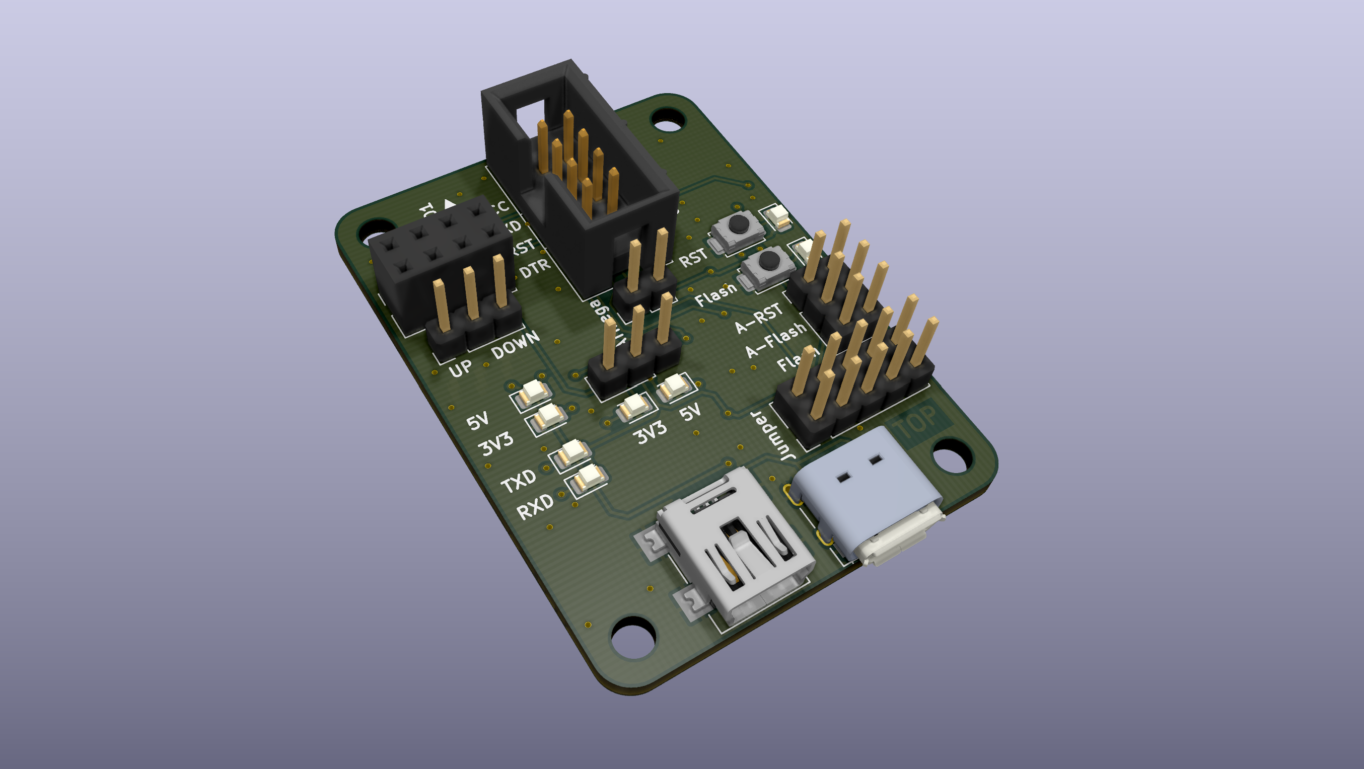
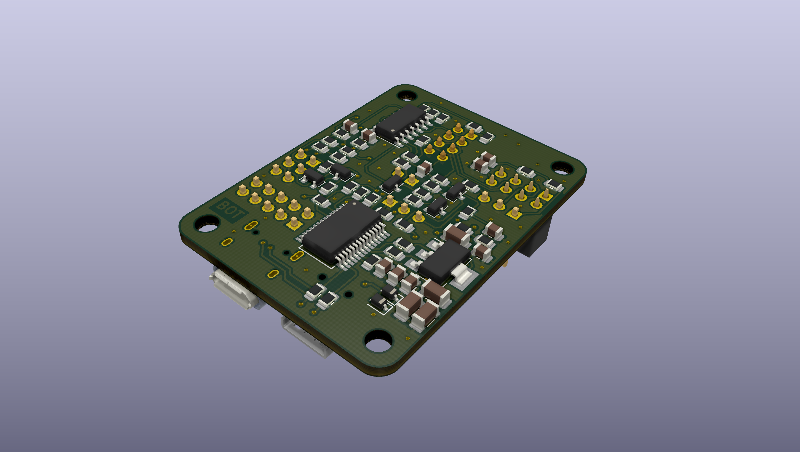
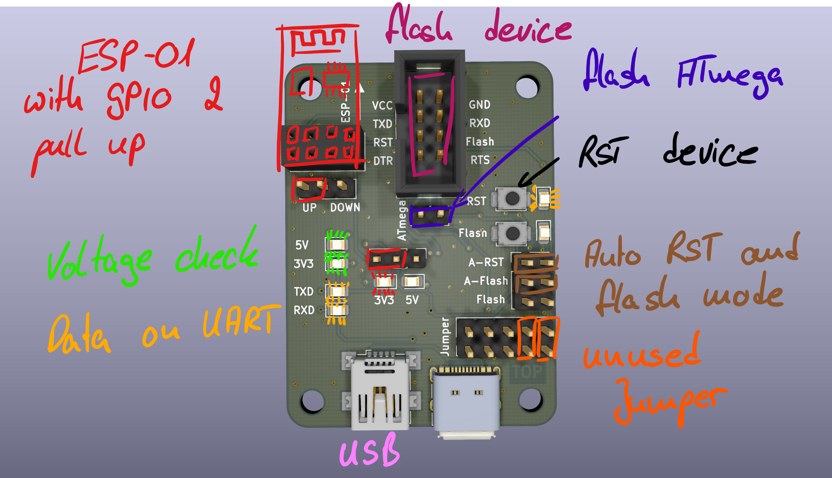
Gerber and drilling data are in the repository. Component placement
No stand-alone software is needed. Use esptool.py or e.g. VS Code for programming.
| Qty | Value | Footprint | References |
|---|---|---|---|
| 15 | 10k | Resistor_SMD:R_0805_2012Metric | R1, R2, R6, R7, R8, R16, R18, R21, R24, R27, R28, R30, R32, R36, R37 |
| 11 | 1k | Resistor_SMD:R_0805_2012Metric | R4, R11, R17, R19, R20, R22, R23, R25, R29, R31, R33 |
| 6 | 100R | Resistor_SMD:R_0805_2012Metric | R9, R10, R12, R13, R14, R15 |
| 6 | 100n | Capacitor_SMD:C_0805_2012Metric | C1, C7, C9, C12, C13, C14 |
| 4 | 4µ7 | Capacitor_SMD:C_1206_3216Metric | C3, C4, C10, C11 |
| 4 | BC847 | Package_TO_SOT_SMD:SOT-23 | Q2, Q3, Q4, Q5 |
| 4 | LED_GREEN | LED_SMD:LED_0805_2012Metric | D3, D4, D6, D8 |
| 4 | MountingHole | MountingHole:MountingHole_3.2mm_M3 | H1, H2, H3, H4 |
| 3 | 470R | Resistor_SMD:R_0805_2012Metric | R3, R34, R35 |
| 2 | 10n | Capacitor_SMD:C_0805_2012Metric | C6, C8 |
| 2 | 1µ | Capacitor_SMD:C_0805_2012Metric | C2, C5 |
| 2 | BAT46WJ | Diode_SMD:D_SOD-323 | D1, D2 |
| 2 | Jumper_3_Bridged12 | Connector_PinHeader_2.54mm:PinHeader_1x03_P2.54mm_Vertical | JP1, JP2 |
| 2 | LED_RED | LED_SMD:LED_0805_2012Metric | D5, D7 |
| 2 | LED_YELLOW | LED_SMD:LED_0805_2012Metric | D9, D10 |
| 2 | SW_Push | Button_Switch_SMD_User:SW_Push_SPST_4x3x2 | SW1, SW2 |
| 1 | 0R | Resistor_SMD:R_0805_2012Metric | R26 |
| 1 | 47R | Resistor_SMD:R_0805_2012Metric | R5 |
| 1 | AMS1117-3.3 | Package_TO_SOT_SMD:SOT-223-3_TabPin2 | U1 |
| 1 | BC857 | Package_TO_SOT_SMD:SOT-23 | Q1 |
| 1 | Conn_01x02_Male | Connector_PinHeader_2.54mm:PinHeader_1x02_P2.54mm_Vertical | J2 |
| 1 | Conn_02x03_Odd_Even | Connector_PinHeader_2.54mm:PinHeader_2x03_P2.54mm_Vertical | J7 |
| 1 | Conn_02x04_Odd_Even | Connector_PinSocket_2.54mm:PinSocket_2x04_P2.54mm_Vertical | J3 |
| 1 | Conn_02x04_Odd_Even | Connector_PinHeader_2.54mm_User:PinHeader_2x04_P2.54mm_Vertical | J5 |
| 1 | Conn_02x05_Odd_Even | Connector_PinHeader_2.54mm:PinHeader_2x05_P2.54mm_Vertical | J1 |
| 1 | FT232RL | Package_SO:SSOP-28_5.3x10.2mm_P0.65mm | U3 |
| 1 | LM339 | Package_SO:SOIC-14_3.9x8.7mm_P1.27mm | U2 |
| 1 | USB_B_Micro | Connector_USB:USB_Micro-B_Molex_47346-0001 | J6 |
| 1 | USB_B_Mini | Connector_USB_User:USB_Mini-B_Wuerth_65100516121_Horizontal | J4 |
| 1 | USB_C_Plug_USB2.0 | Connector_USB_User:USB_C_Receptacle_XKB_U262-16XN-4BVC11 | P1 |
It measures 37 × 50 mm and has 2 copper layers, 1.6 mm thick.
85 parts, built around the FT232RL, AMS1117-3.3, LM339 and BC847. The full list of its parts is on this page, with links to each part's symbol and footprint where PCBKit's library has them.
From the eike2511/uart_flash_pcb repository on GitHub, at the commit this page was made from: the board is uart_flash_pcb.kicad_pcb and its schematic uart_flash_pcb.kicad_sch. PCBKit opens the board in the browser, with nothing to install.
Its repository publishes it under the GPL-3.0 licence: you may reuse it on that licence's terms (keep the author's notice, and for a copyleft licence share your changes alike).

MadsRudolph/vinyl-adc
Discrete 3rd-order delta-sigma stereo audio ADC, built from op-amps and logic gates: a four-layer Raspberry Pi HAT made by PCBWay, with KiCad files, SPICE simulations and measurements

dm2lct/tlnixie
PCB files for the Turmlabor nixie clock 2.0


Fihdi/MiniDrumkit
Eurorack DrumKit module with a 3 channel wave-file player and analog Hi-Hat and Kick Drum sections

slqa/aquarea_esphome
I used hardware serial on pins GPIO15/GPIO13 and one pin for RTS from a GPIO5 Mini ESP board. In a 'normal' situation, the ESP12E only listens to communication between the remote and the heat pump, so you can have…

shreya2717/Solar-Rooftop-Financing-Market-Risk-Analysis
Solar energy is the cleanest and most available renewable energy source. The Modern technology can harness this energy for a variety of uses, including producing electricity, providing light and heating water for…

akornsys-rdi/high-torque-servo-arm
High torque servo arm, the system behind «Llegar a las manos» artwork