
4 layers162.2 × 126.4 mm

 eggsacc/pcb-MeowCU
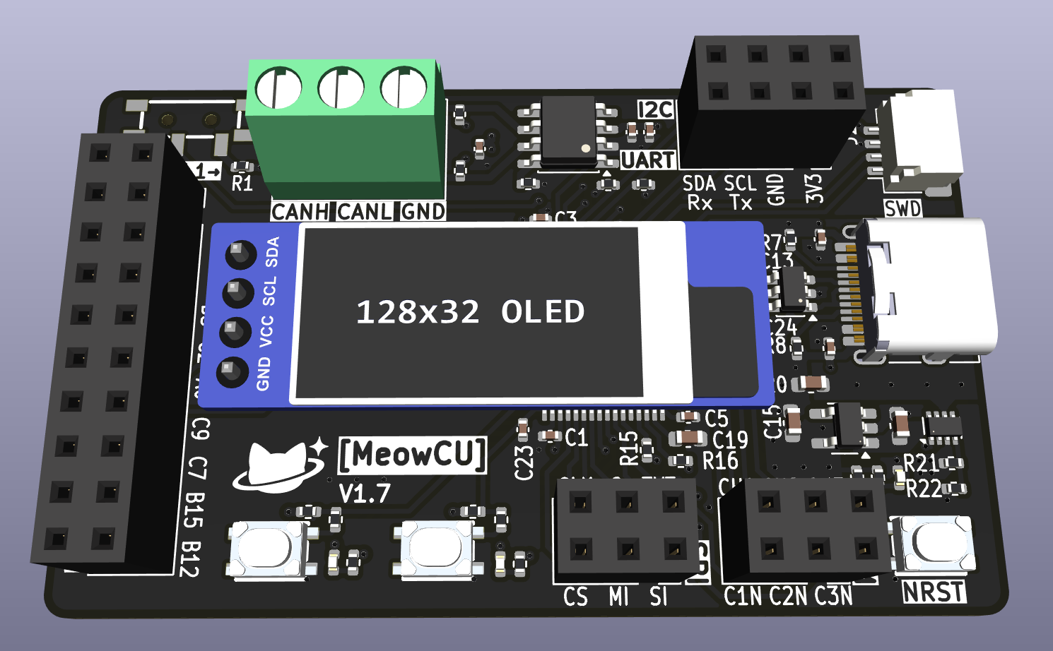
4-layer STM32F405RGT6 MeowCU 🐱 (MCU) dev module with commonly used peripherals broken out for easy access, and a dedicated CAN transceiver. Also includes 2 user programmable buttons and mini OLED display.
MeowCU is an open-source printed circuit board by eggsacc, from the eggsacc/pcb-MeowCU repository on GitHub. It is a 4-layer board of 58.7 × 35.5 mm with 69 parts on 93 nets, routed with 557 tracks and 122 vias.
It is built around the STM32F405RGT6, SN65HVD230D and AP2112K-3.3, with the TPS2116DRL and USBLC6-2SC6 among its other parts. Its parts include 23 capacitors, 20 resistors, 8 connectors, 5 ICs and 3 diodes. It belongs with the STM32 boards of this library.




4-layer STM32F405RGT6 MeowCU 🐱 (MCU) dev module with commonly used peripherals broken out for easy access, and a dedicated CAN transceiver. Also includes 2 user programmable buttons and mini OLED display.
3D render - Front
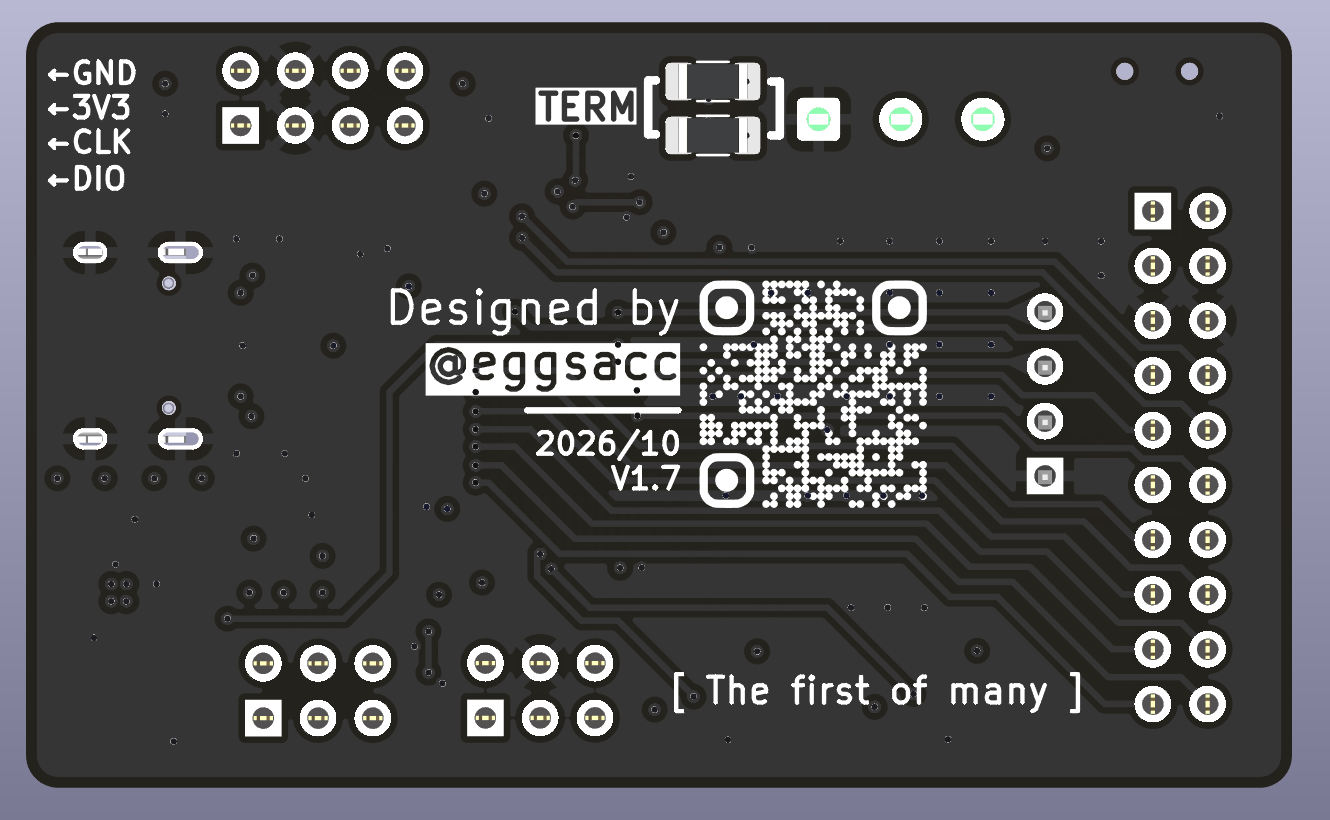
Back
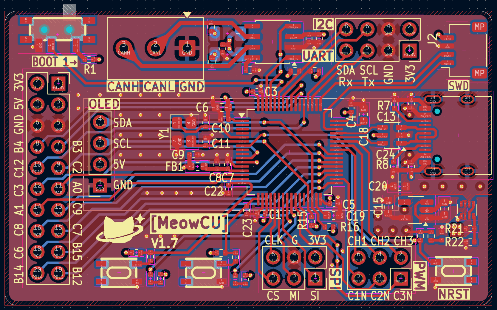
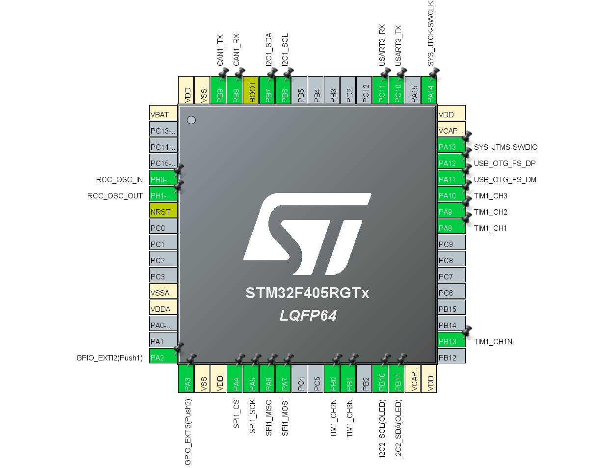
| Breakout / feature | Peripheral | Pin mapping | ||||||||||||||||||||||||||||||||||||||||
|---|---|---|---|---|---|---|---|---|---|---|---|---|---|---|---|---|---|---|---|---|---|---|---|---|---|---|---|---|---|---|---|---|---|---|---|---|---|---|---|---|---|---|
| UART header | USART3 | TX → PC10RX → PC11 | ||||||||||||||||||||||||||||||||||||||||
| SPI header | SPI1 | CS → PA4SCK → PA5MISO → PA6MOSI → PA7 | ||||||||||||||||||||||||||||||||||||||||
| I2C header | I2C1 | SCL → PB6SDA → PB7 | ||||||||||||||||||||||||||||||||||||||||
| CAN screw terminal | CAN1 (SN65HVD230) | TX → PB9RX → PB8 | ||||||||||||||||||||||||||||||||||||||||
| USB-C | USB_OTG_FS | D− → PA11D+ → PA12 | ||||||||||||||||||||||||||||||||||||||||
| SWD header | SYS | SWDIO → PA13SWCLK → PA14 | ||||||||||||||||||||||||||||||||||||||||
| 3-phase PWM header | TIM1 |
| ||||||||||||||||||||||||||||||||||||||||
| OLED (on-board) | I2C2 | SCL → PB10SDA → PB11 | ||||||||||||||||||||||||||||||||||||||||
| Utility buttons (on-board) | GPIO / EXTI | L button → PA2R button → PA3 | ||||||||||||||||||||||||||||||||||||||||
| Crystal (25MHz) | RCC HSE | OSC_IN → PH0OSC_OUT → PH1 | ||||||||||||||||||||||||||||||||||||||||
| GPIO header (2×10) | free GPIO |
|
*Buttons are active-low to GND (3V3 pull-up).
The external 5V pin and USB vbus are separate rails; a power mux IC (TPS2116) automatically switches to the external 5V rail when connected.
| Qty | Value | Footprint | References |
|---|---|---|---|
| 10 | 100n | Capacitor_SMD:C_0402_1005Metric | C2, C3, C4, C5, C6, C10, C11, C12, C13, C22 |
| 6 | 10k | Resistor_SMD:R_0402_1005Metric | R1, R4, R6, R10, R18, R20 |
| 4 | 4k7 | Resistor_SMD:R_0402_1005Metric | R11, R12, R14, R15 |
| 4 | 4u7 | Capacitor_SMD:C_0603_1608Metric | C1, C14, C19, C20 |
| 3 | 1u | Capacitor_SMD:C_0402_1005Metric | C8, C9, C21 |
| 3 | 470 | Resistor_SMD:R_0402_1005Metric | R2, R3, R13 |
| 3 | BTN_UTIL | addons:SW-SMD_4P-L4.2-W3.4-P2.15-LS5.2 | SW1, SW2, SW3 |
| 3 | GREEN | LED_SMD:LED_0402_1005Metric | D1, D2, D3 |
| 2 | 100 | Resistor_SMD:R_0402_1005Metric | R5, R7 |
| 2 | 10n | Capacitor_SMD:C_0402_1005Metric | C7, C23 |
| 2 | 14p | Capacitor_SMD:C_0402_1005Metric | C15, C16 |
| 2 | 2u2 | Capacitor_SMD:C_0603_1608Metric | C17, C18 |
| 2 | 5k1 | Resistor_SMD:R_0402_1005Metric | R8, R9 |
| 2 | 60 | Resistor_SMD:R_0402_1005Metric | R16, R17 |
| 2 | Conn_02x03_Odd_Even | Connector_PinSocket_2.54mm:PinSocket_2x03_P2.54mm_Vertical | J4, J6 |
| 2 | LOGO | LOGO | G***, G*** |
| 2 | SolderJumper_2_Bridged | Jumper:SolderJumper-2_P1.3mm_Bridged_RoundedPad1.0x1.5mm | JP1, JP2 |
| 1 | 120R | Inductor_SMD:L_0603_1608Metric | FB1 |
| 1 | 25MHz | Crystal:Crystal_SMD_3225-4Pin_3.2x2.5mm | Y1 |
| 1 | 30k | Resistor_SMD:R_0402_1005Metric | R19 |
| 1 | AP2112K-3.3 | Package_TO_SOT_SMD:SOT-23-5_HandSoldering | U3 |
| 1 | Conn_02x10_Odd_Even | Connector_PinSocket_2.54mm:PinSocket_2x10_P2.54mm_Vertical | J1 |
| 1 | I2C1/USART3 | Connector_PinSocket_2.54mm:PinSocket_2x04_P2.54mm_Vertical | J3 |
| 1 | MSK-11027 Toggle Switches | addons:SW-SMD_MSK-11027 | KEY1 |
| 1 | OLED | addons:OLED header | J5 |
| 1 | SN65HVD230 | Package_SO:SOIC-8_3.9x4.9mm_P1.27mm | U4 |
| 1 | STM32F405RGT6 | Package_QFP:LQFP-64_10x10mm_P0.5mm | U1 |
| 1 | SWD | Connector_JST:JST_SH_SM04B-SRSS-TB_1x04-1MP_P1.00mm_Horizontal | J7 |
| 1 | Screw_Terminal_01x03 | TerminalBlock_Phoenix:TerminalBlock_Phoenix_MKDS-1-3-3.81_1x03_P3.81mm_Horizontal | J8 |
| 1 | TPS2116DRL | Package_TO_SOT_SMD:SOT-583-8 | U5 |
| 1 | USBLC6-2SC6 | Package_TO_SOT_SMD:SOT-23-6 | U2 |
| 1 | USB_C_Receptacle_USB2.0_16P | Connector_USB:USB_C_Receptacle_HRO_TYPE-C-31-M-12 | J2 |

fwillard/CANTranslate
The hardware design for CANTranslate facilitates physical interfacing and electrical translation between multiple CAN bus systems.

Isaac-Duarte/wellfed
Open firmware that runs the PETLIBRO Granary PLAF103 pet feeder on your own Wi-Fi: no cloud, no account. Early and in testing.


MAIK97MAX/mini-climate-control
A miniature climate control unit which is remotely controlled

GabuGravin41/rlpcb
RL PCB sits beside KiCad and works like a senior hardware engineer looking over your shoulder. You describe what you want to build; it helps you choose real parts from your KiCad libraries, works out the values, places…

ajisrawi/5g-3d-printed-drone
3D-printed quadcopter with a custom F405 flight controller, 4G/5G companion connectivity, and phone control

It measures 58.7 × 35.5 mm and has 4 copper layers, 1.61 mm thick.
69 parts, built around the STM32F405RGT6, SN65HVD230D, AP2112K-3.3 and TPS2116DRL. The full list of its parts is on this page, with links to each part's symbol and footprint where PCBKit's library has them.
From the eggsacc/pcb-MeowCU repository on GitHub, at the commit this page was made from: the board is MeowCU/MeowCU.kicad_pcb and its schematic MeowCU/MeowCU.kicad_sch. PCBKit opens the board in the browser, with nothing to install.
Its repository states no licence, so its author keeps all rights: ask eggsacc before reusing the design.