
2 layers30 × 32 mm

 EeBbHh/wristwatch
wrist watch prototype
ProtoboardV2 is an open-source printed circuit board by EeBbHh, from the EeBbHh/wristwatch repository on GitHub, published under the MIT licence. It is a 2-layer board of 26 × 28 mm with 17 parts on 10 nets, routed with 36 tracks and 2 vias.
It is built around the SS14. Its parts include 6 connectors, 2 resistors, 2 diodes, 2 transistors and 2 switches.
Disclaimer. This is a work in progress. Open source proof of concept provided. Screenshots and video provided. Documentation is subject to change.
NOTICE! Due to memory limits a second python file was created. sprites.py is required. Place next to code.py in the CIRCUITPY drive. The follwing lines need to be added to boot.py: "import displayio" and below that "displayio.release_displays()"
Clock + Metronome + Tuner wristwatch is the goal of this project. In addition. There are standalone files for each mode.
Dev Enviornment: Mu https://codewith.mu/en/, KiCAD https://www.kicad.org/
Circuitpython for QTpy RP2040: https://circuitpython.org/board/adafruit_qtpy_rp2040/
Circuitpython 10.x libraries: https://circuitpython.org/libraries
NOTE: Place the following in the lib folder: adafruit_bus_device folder, adafruit_display_text folder, adafruit_gc9a01a.mpy and adafruit_ticks.mpy.
NOTE: Add the following to the requirements folder: adafruit_bus_device folder, adafruit_display_text folder and adafruit_gc9a01a folder.
Microcontroller: QTpy RP2040 https://www.adafruit.com/product/4900
Special thanks to these two projects that got me started on this journey. https://projecthub.arduino.cc/petbump10/arduino-tick-tock-metronome-a49188 and https://github.com/FoamyGuy/Adafruit_CircuitPython_Display_AnalogClock
Prototype 1, 2 and 3 Display: 1.28" Round TFT https://www.adafruit.com/product/6178
Prototype 1 hardware: EYESPI BFF https://www.adafruit.com/product/5772, IoT Button BFF https://www.adafruit.com/product/5666, Vibration Mini Motor https://www.adafruit.com/product/1201, Piezo Buzzer https://www.adafruit.com/product/1740, LIPO Charger BFF https://www.adafruit.com/product/5397, 400mAh LIPO Battery https://www.adafruit.com/product/3898
Prototype 2 hardware: IoT Button BFF removed. Prototype board added. SMD parts replace THT parts. All SMD parts purchsed from https://www.digikey.com/ Buttons added. Piezo replaced with magnetic transducer. Schematic and board file provided.
Prototype 3 hardware: EYESPI BFF removed. Prototype board updated. SMD FPC added. SMD vibration motor replaces THT vibration motor. 420mAh LIPO battery https://www.adafruit.com/product/4236 replaces 400mAh LIPO battery.
Prototype 4 hardware: Prototype board updated. New 1.28 Display https://www.buydisplay.com/1-28-inch-tft-lcd-display-240x240-round-circle-screen-for-smart-watch, SMD FPC updated. QTpy dock added. Futher refinement is underway as I put protoboardV4 through testing.
Prototype 5 hardware: Circuit for display reset added. Circuit for backlight added. QTpy dock adjusted from 17.5mm to 18mm. Prototype board version 5 sits at 25mm.
Prototype 6 hardware: Lipo BFF circuitry absorbed to further reduce height of the stack. Final iteration for 6 will have the female headers removed and vibration motor moved out of the way for soldering the QTpy closer to the board. Prototype board version 6 sits at 11.30mm. Goal is to get closer to 13 with case.
Prototype 7 hardware: Through hole side actuated buttons replaced Surface mount top actuated buttons. Test pads replaced through hole connectors for battery.
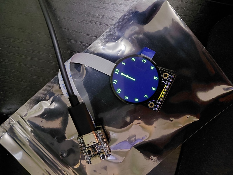
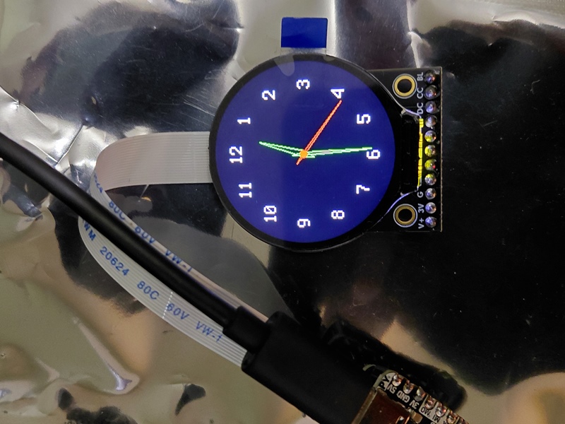
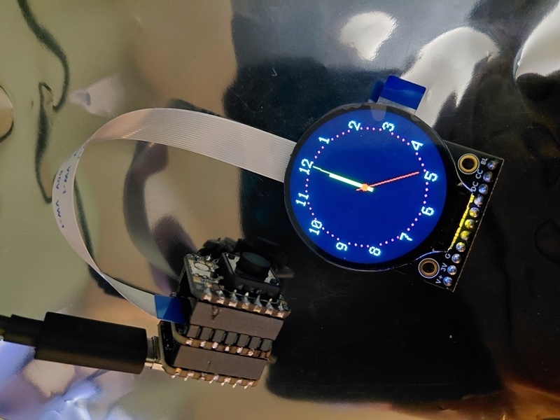
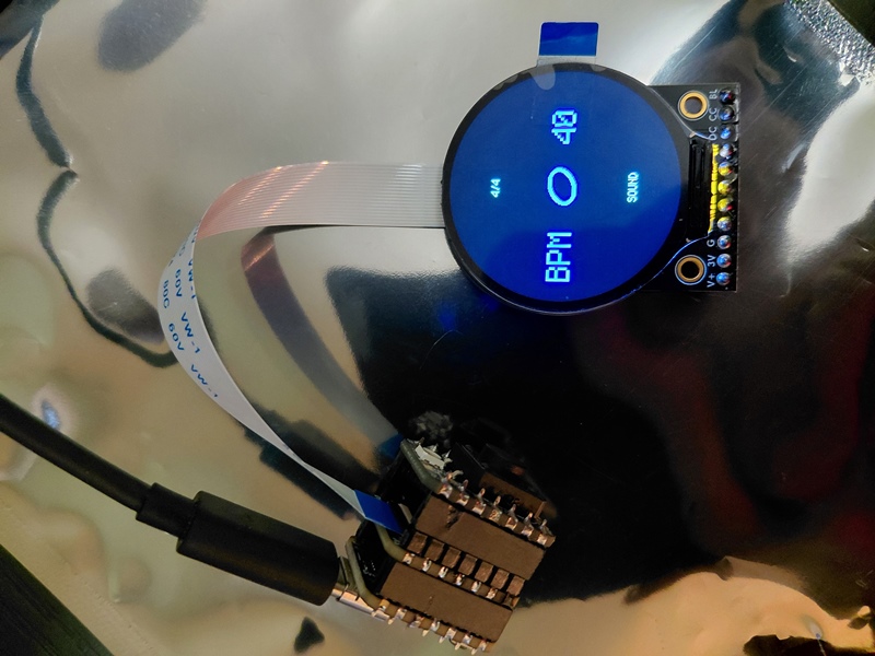
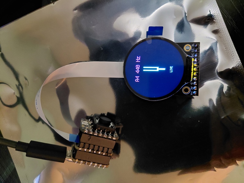
https://github.com/user-attachments/assets/00a04122-98c7-4e2a-a195-a43d13c6c467
Vibration circuit layout. A transistor and resistor are used to make it possible for the QTpy to control the motor with 3 volts. A diode is used as a flyback for when the motor stops running. The transistor connects to the black wire, the resistor and the diode. The black wire goes from the emitter lead of the transistor to ground. The resistor(100ohm) connects the base lead of the transistor to A1. The anode portion of the diode connects to the collector lead of the transistor. The cathode porton of the diode connects to the red wire. The red wire connects to 3.3 volts. The driver motor connects to each side of the diode. Blue to anode and red to cathode.
Component list: 100Ω resistor, diode(1N4007) and transistor(2N2222)
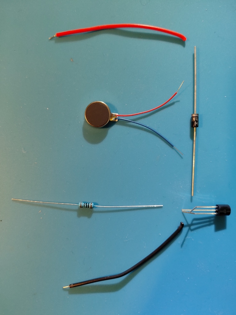
Soldered vibration circuit.
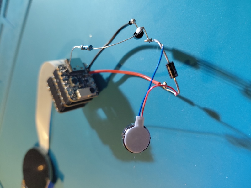
https://github.com/user-attachments/assets/0c229e03-611d-4f90-9194-24d2ad153cdb
Soldered piezo.
https://github.com/user-attachments/assets/ea14efcf-dfc6-47f1-8c45-b138b7211cc2
LIPO BFF added. Backlight hack added(red wire at the top) to allow for screen dimming as a battery saving feature.
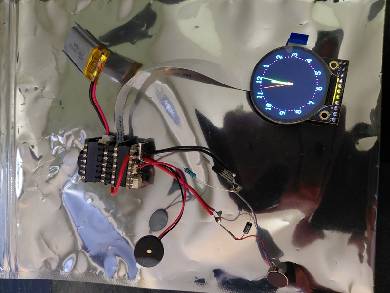
Screen dimming test. At the 10 second mark the screen dims.
https://github.com/user-attachments/assets/76fc044c-b8f3-486a-8c0e-50453308a22c
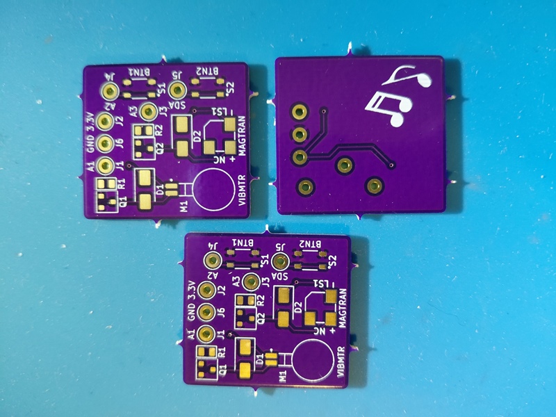
Prototype 2 board screenshots. Pre and post solder.
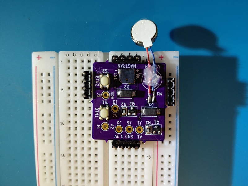
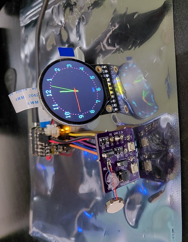
Prototype 3 board screenshots. Pre and post solder.
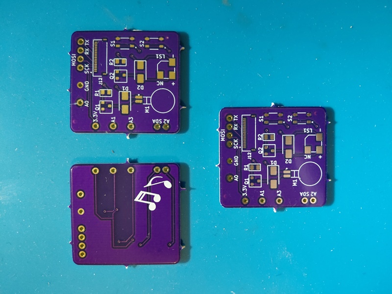
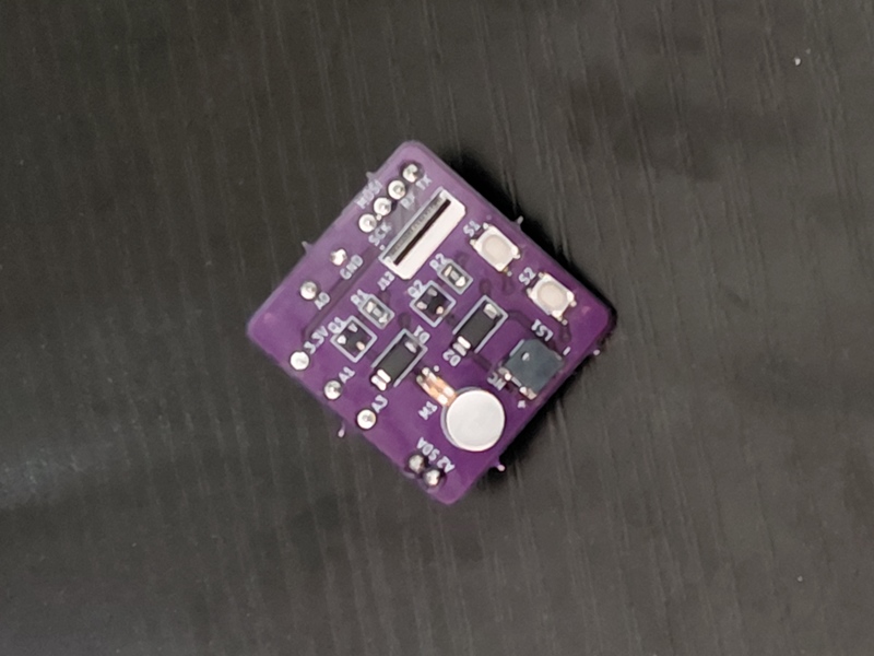
Prototype 4a board screenshots. Pre and post solder.
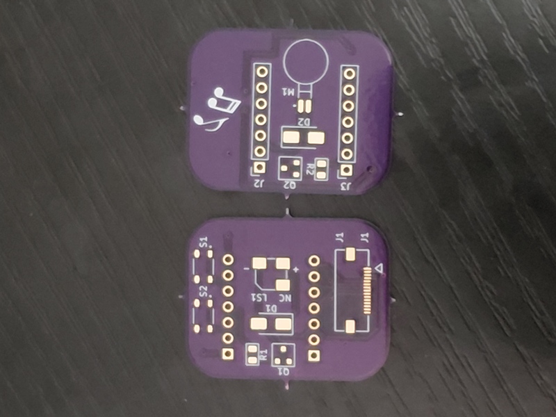
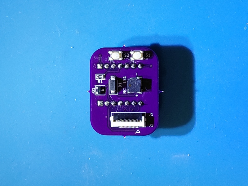
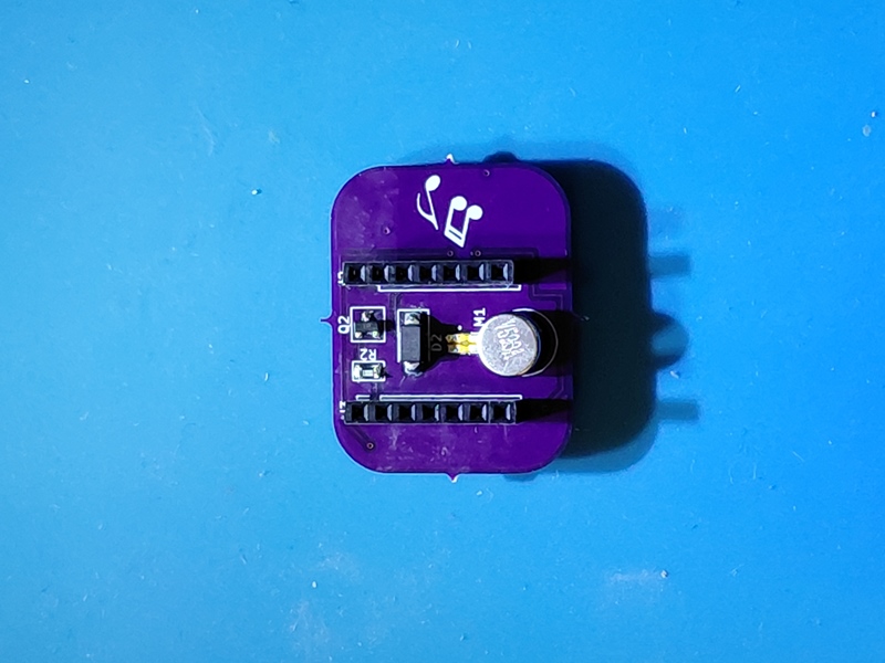
Prototype 5a board screenshots. Pre and post solder.
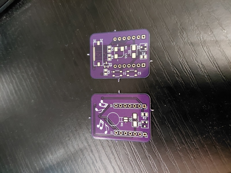
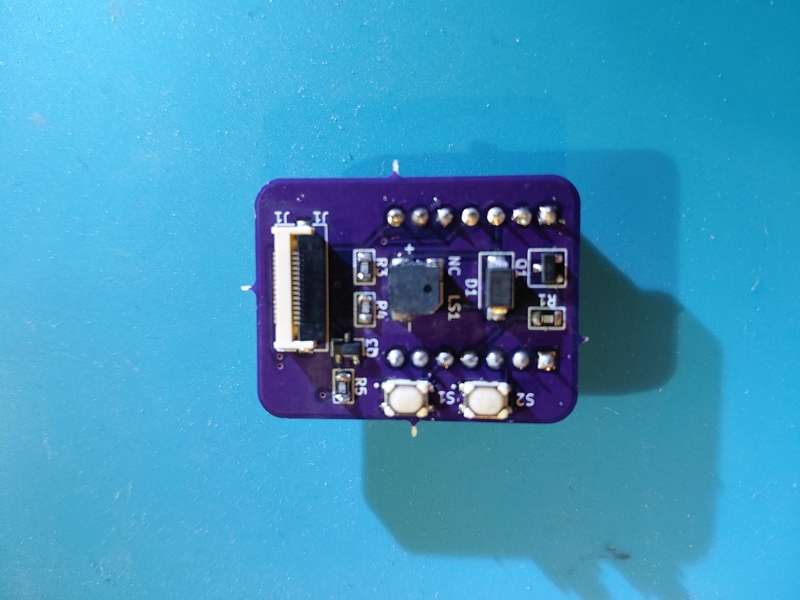
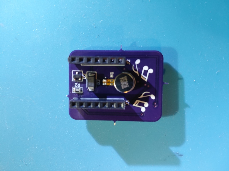
Prototype 5b board screenshots. Pre and post solder.
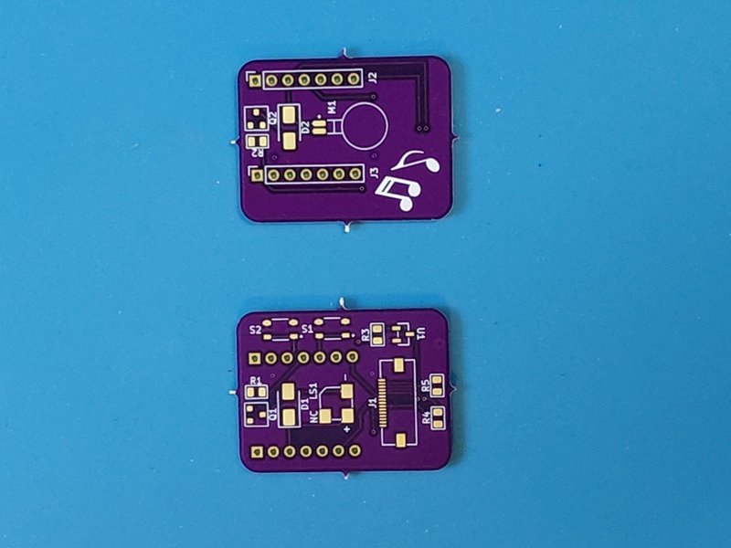
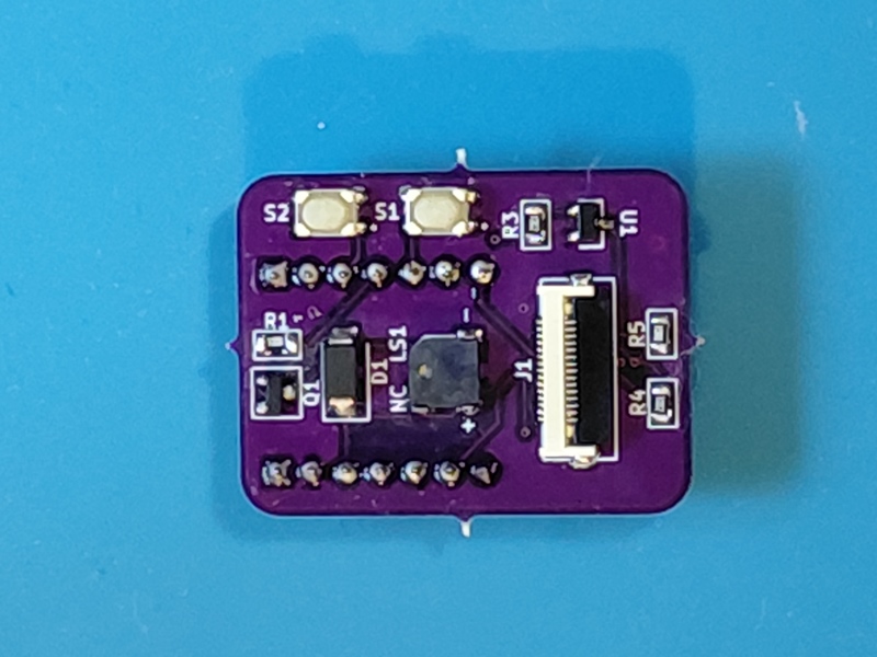
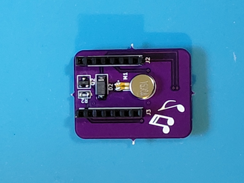
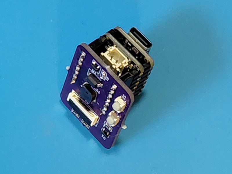
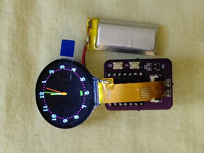
Prototype 6a board screenshots. Pre and post solder.
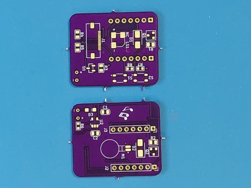
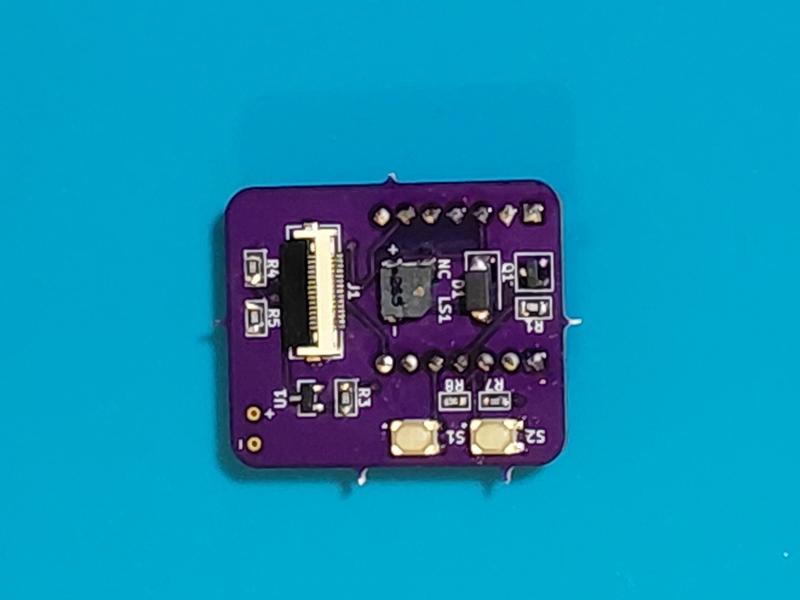
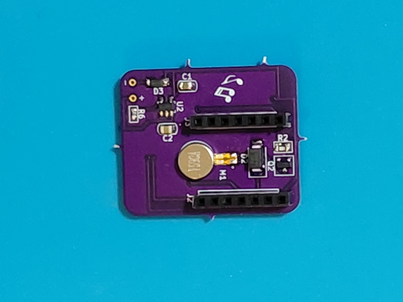
Prototype 6b board screenshots. Pre and post solder.
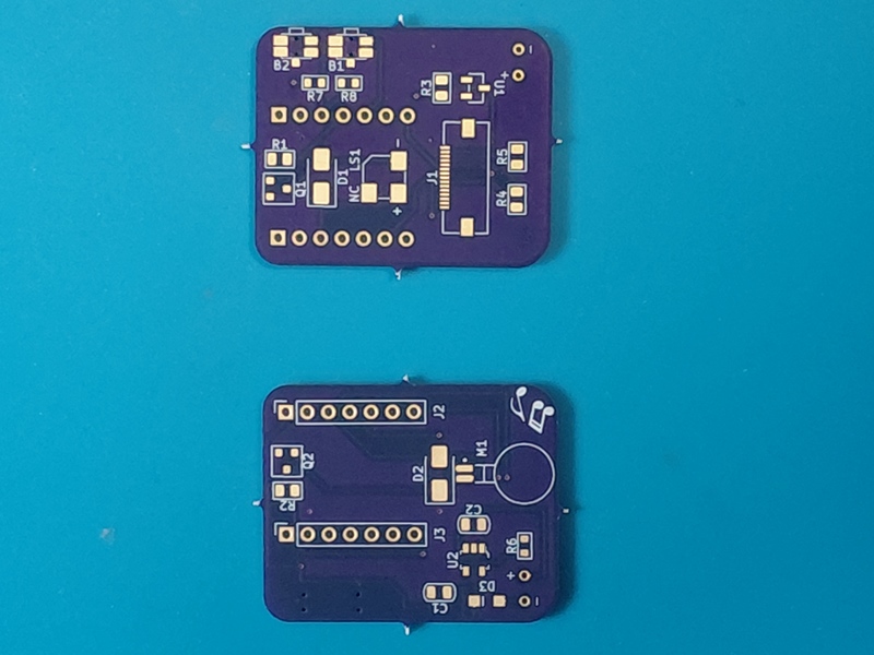
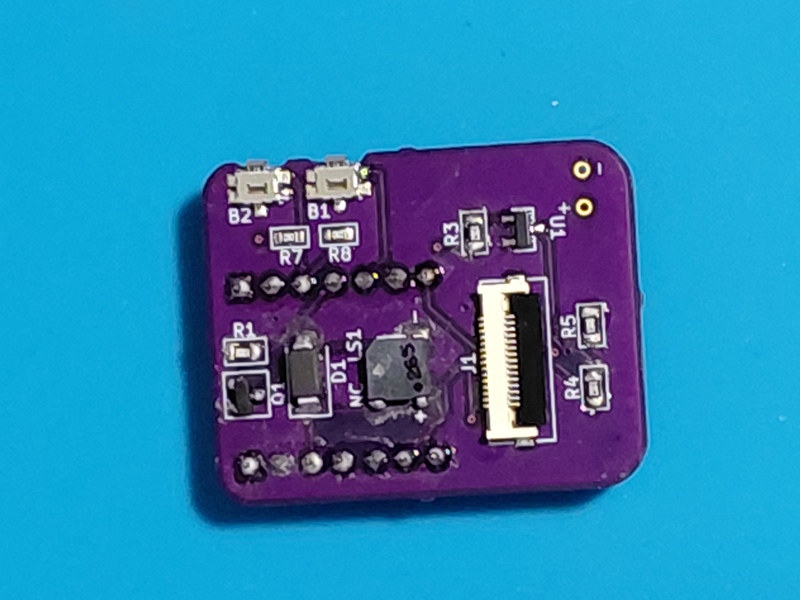
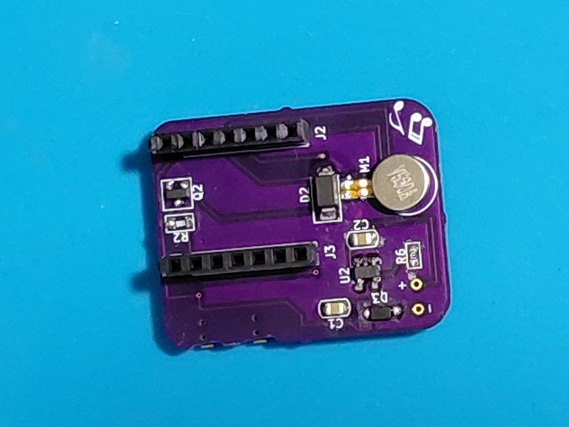
Prototype 6c board screenshots. Pre and post solder.
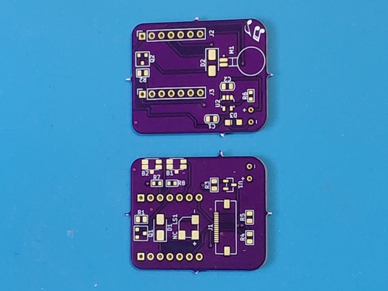
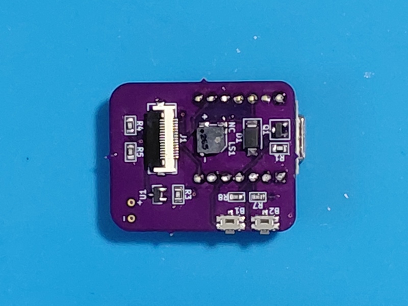
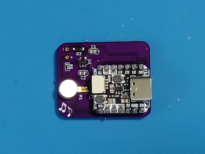
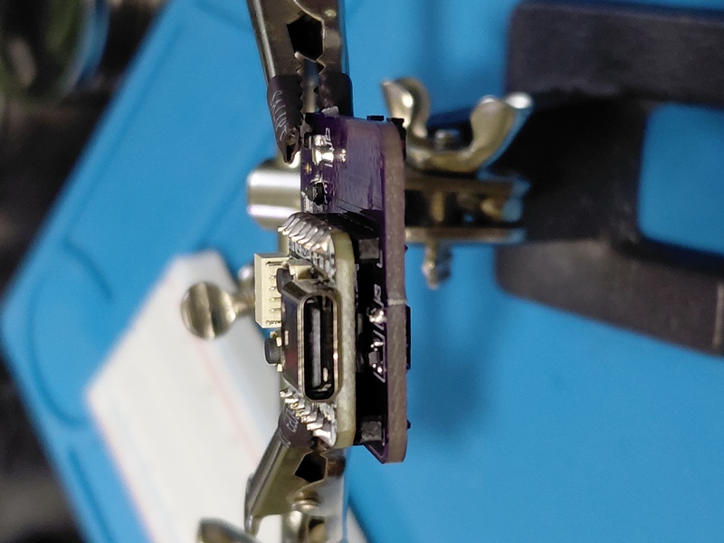
Prototype 6d board screenshots. Pre and post solder.
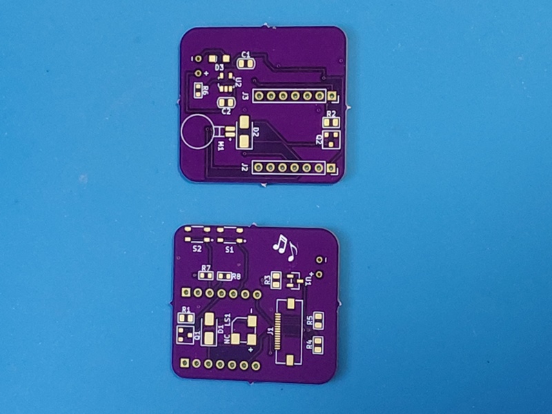
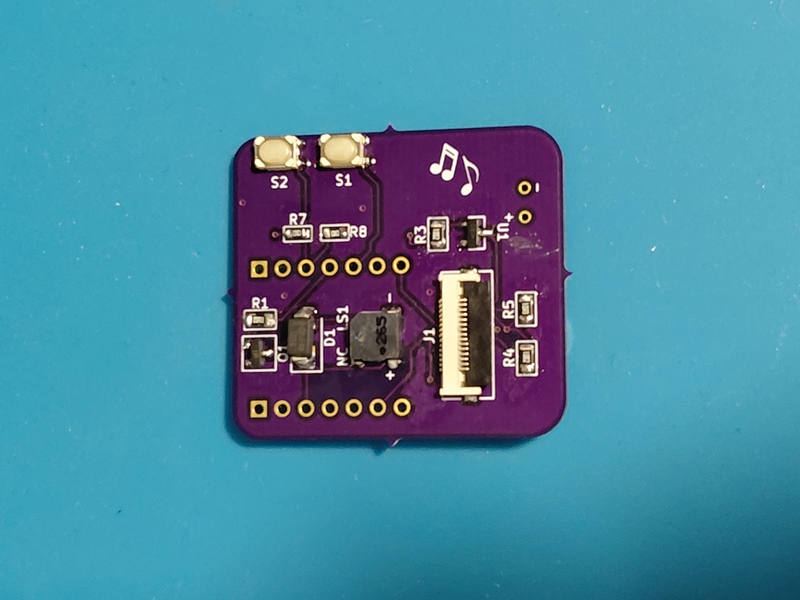
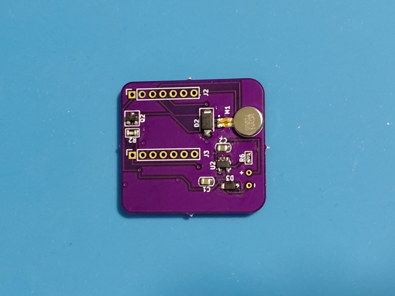
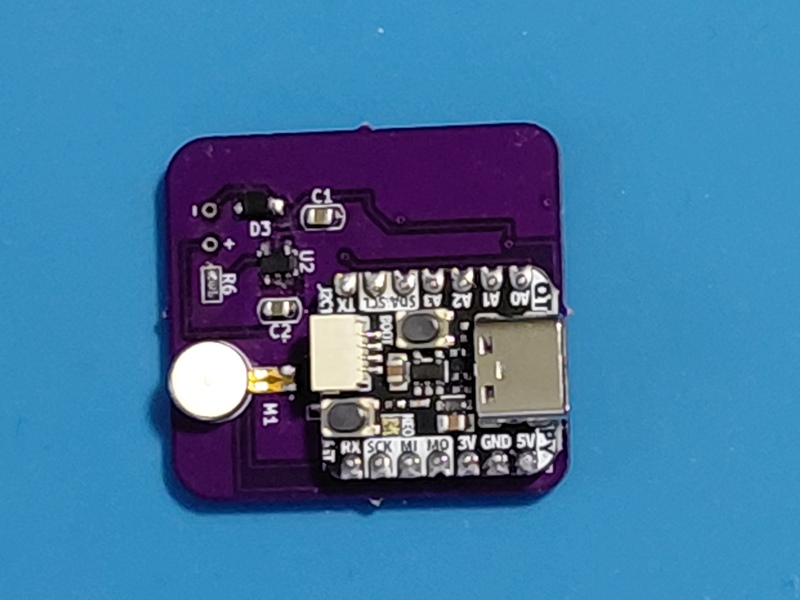
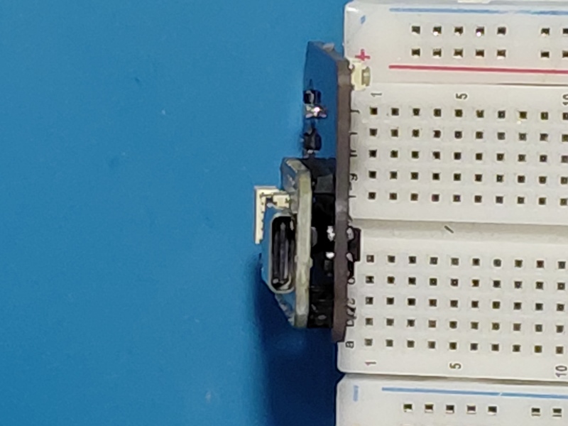
| Qty | Value | Footprint | References |
|---|---|---|---|
| 2 | 100R | PCM_Resistor_SMD_AKL:R_0805_2012Metric | R1, R2 |
| 2 | SS14 | Diode_SMD:D_SMA | D1, D2 |
| 1 | 3.3V | Connector_Pin:Pin_D1.0mm_L10.0mm_LooseFit | J2 |
| 1 | A1 | Connector_Pin:Pin_D1.0mm_L10.0mm_LooseFit | J1 |
| 1 | A2 | Connector_Pin:Pin_D1.0mm_L10.0mm_LooseFit | J4 |
| 1 | A3 | Connector_Pin:Pin_D1.0mm_L10.0mm_LooseFit | J3 |
| 1 | BTN1 | SKRPABE010:SW_SKRPABE010 | S1 |
| 1 | BTN2 | SKRPABE010:SW_SKRPABE010 | S2 |
| 1 | GND | Connector_Pin:Pin_D1.0mm_L10.0mm_LooseFit | J6 |
| 1 | LOGO | LOGO | G*** |
| 1 | MAGTRAN | CSS-0575A-SMT:CUI_CSS-0575A-SMT | LS1 |
| 1 | NPN1 | PCM_Package_TO_SOT_SMD_AKL:SOT-23 | Q1 |
| 1 | NPN2 | PCM_Package_TO_SOT_SMD_AKL:SOT-23 | Q2 |
| 1 | SDA | Connector_Pin:Pin_D1.0mm_L10.0mm_LooseFit | J5 |
| 1 | VIBMTR | C0720B001F:XDCR_C0720B001F | M1 |


JGAguado/Smart_Plant
The Smart Plant is a board that can be plugged directly on the soil, close to the plant, that allows the measurement of the environment (soil moisture, environment temperature & illuminance), and presents the…

ugcs/ddc
Drone Show Software is software designed for drone shows, allowing flight path planning as well as control of dozens of drones simultaneously in a synchronized manner.

eddyem/stm32samples
Code samples and ready projects based on bare-metal STM32


execuc/u2if
USB to interfaces implementing MicroPython "machine" module functionalities on a computer.

ZeroPhone/ZeroPhone-PCBs
PCB files for ZeroPhone - for gerbers and schematics, go to "Releases" tab!

It measures 26 × 28 mm and has 2 copper layers, 1.6 mm thick.
17 parts, built around the SS14. The full list of its parts is on this page, with links to each part's symbol and footprint where PCBKit's library has them.
From the EeBbHh/wristwatch repository on GitHub, at the commit this page was made from: the board is protoboardV2.kicad_pcb and its schematic protoboardV2.kicad_sch. PCBKit opens the board in the browser, with nothing to install.
Its repository publishes it under the MIT licence: you may reuse it on that licence's terms (keep the author's notice, and for a copyleft licence share your changes alike).