
2 layers63.5 × 63.5 mm
Main pcb
peterkrull/quad
Firmware, hardware and documentation for my autonomous quad copter project
45 parts210GPL-3.0

 e-zsche/FV-1-standalone-programmer1
Standalone programmer for assembling and programming FV-1 programs onto 24LC32A EEPROMS
FV-1 EEPROM flasher hardware is an open-source printed circuit board by e-zsche, from the e-zsche/FV-1-standalone-programmer repository on GitHub. It is a 2-layer board of 64.9 × 89.1 mm with 22 parts on 44 nets, routed with 213 tracks and 36 vias.
It is built around the 24LC32A/P. Its parts include 8 resistors, 6 switches, 2 capacitors, 2 ICs and 1 diode. It belongs with the interfaces and adapters boards and the RP2040 boards of this library.
Small project for flashing 24LC32A EEPROMs using any microcontroller which has enough flash and is able to run Micropython. Just because, a raspberry pico is used.
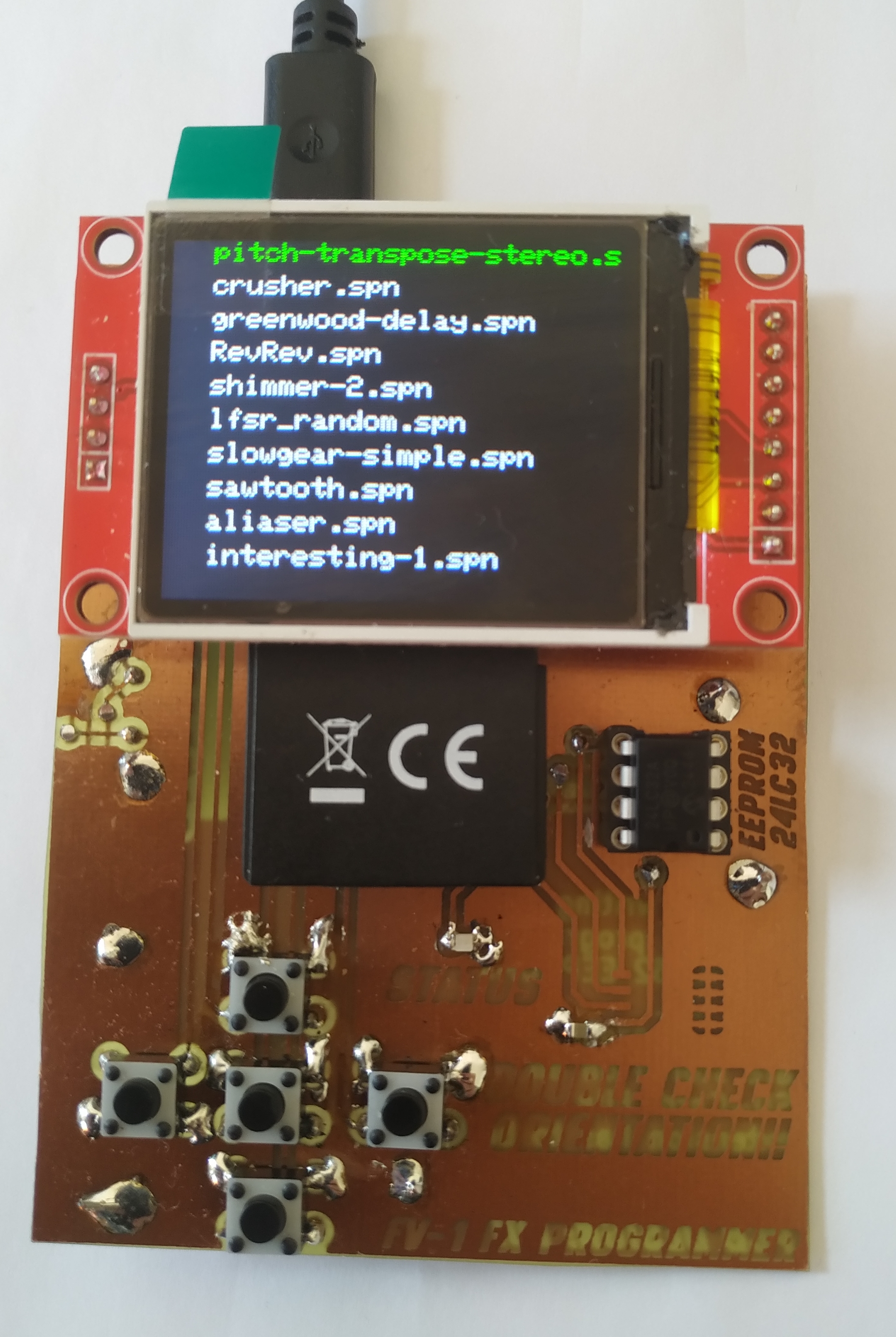
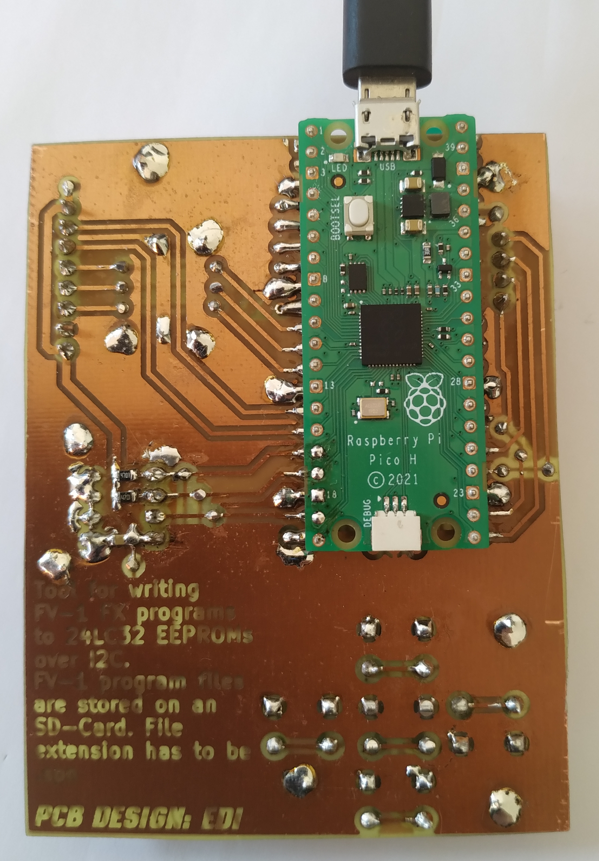
Huge thanks to ndf-zz for writing the asfv1 assembler. Without your work this would not be possible. https://github.com/ndf-zz/asfv1/
As shlex is not in the standard Micropython library a copy of the source code is obtained and used for running the asfv1 assembler. To get it running on the MCU one line is removed. So far this does not seem to have an impact when running the code.
FV-1 programs are stored and read with a micro SD-card. All programs have to be in the root directory
and must have the .spn file extension to be found.
Everything is run by a Raspberry Pi Pico MCU.
User interface consists of:
TFT display because it is cheaper than an OLED. Has the SD card slot integrated.
Connected via SPI. Slot is Integrated into display module.
There are two positions on the PCB. One is for THT chips, the other for SMD chips. SMD socket is the SOIC-8 socket from adafruit
Make sure to insert the EEPROM with the correct orientation!!
In total there are five buttons arranged as a sort of D-Pad and a shift button.
Controls:
Writing programs yourself for the FV-1 is good way to get some programs. Info on the assembly language is a little harder to find than info on the FV-1 hardware. However there are some sources inside a forum dating back to 2019:
This is about all the info I could find on the assembly instructions itself...
Another wonderful source of programs is mstratman's collection of programs:
| Qty | Value | Footprint | References |
|---|---|---|---|
| 8 | 4K7 | Resistor_SMD:R_0805_2012Metric_Pad1.20x1.40mm_HandSolder | R1, R2, R3, R4, R5, R6, R7, R8 |
| 2 | 100n | Allgemein:C_0805 | C1, C2 |
| 2 | select | Button_Switch_THT:SW_PUSH_6mm_H5mm | SW5, SW6 |
| 1 | 24LC32 | Package_SO:SOIC-8_5.3x5.3mm_P1.27mm | U2 |
| 1 | 24LC32 | Package_DIP:DIP-8_W7.62mm_Socket_LongPads | U1 |
| 1 | Down | Button_Switch_THT:SW_PUSH_6mm_H5mm | SW2 |
| 1 | LED | LED_SMD:LED_0805_2012Metric_Pad1.15x1.40mm_HandSolder | D1 |
| 1 | Left | Button_Switch_THT:SW_PUSH_6mm_H5mm | SW4 |
| 1 | RaspberryPi_Pico | Module:RaspberryPi_Pico_SMD | A1 |
| 1 | Right | Button_Switch_THT:SW_PUSH_6mm_H5mm | SW3 |
| 1 | TFT_SD | project_lib:TFT_with_SD | J1 |
| 1 | Up | Button_Switch_THT:SW_PUSH_6mm_H5mm | SW1 |
| 1 | Val** | Allgemein:PCB_EDI_logo | Ref** |
peterkrull/quad
Firmware, hardware and documentation for my autonomous quad copter project

mobilinkd/NucleoTNC
The Nucleo TNC is a breadboard implementation of the Mobilinkd TNC3 using a STM32L432KC Nucleo32 board. This TNC faithfully implements the audio section and EEPROM storage of the TNC3.

MetalMusings/MyOwnEtherCATDevice
Documentation accompanying the "Make My Own EtherCAT device" video serie on Youtube.

mecparts/PicoWiFiModem
A Pico W based RS232 <-> WiFi modem with Hayes AT style commands and LED indicators

dilshan/ir-clone
Open-source infrared remote control signal analysis and generating tool

fietser28/EL-Load
The DCL8010 electronic load module features a DC Electronic Load with several modes and protections. This project is the for the development boards for this project. There is a seperate git project for the firmware.


It measures 64.9 × 89.1 mm and has 2 copper layers, 1.6 mm thick.
22 parts, built around the 24LC32A/P. The full list of its parts is on this page, with links to each part's symbol and footprint where PCBKit's library has them.
From the e-zsche/FV-1-standalone-programmer repository on GitHub, at the commit this page was made from: the board is FV-1_EEPROM_flasher_hardware/FV-1_EEPROM_flasher_hardware.kicad_pcb and its schematic FV-1_EEPROM_flasher_hardware/FV-1_EEPROM_flasher_hardware.kicad_sch. PCBKit opens the board in the browser, with nothing to install.
Its repository states no licence, so its author keeps all rights: ask e-zsche before reusing the design.