2 layers191.1 × 114.3 mm

 DutchMaker/TTL-computer24
Building a computer from scratch using 74xx logic chips
Circuits is an open-source printed circuit board by DutchMaker, from the DutchMaker/TTL-computer repository on GitHub. It is a 2-layer board of 286.4 × 484.5 mm with 58 parts on 171 nets, routed with 1,176 tracks and 21 vias.
Its parts include 39 connectors, 15 capacitors, 1 resistor, 1 IC and 1 diode.
My attempt at building a computer from scratch with 74xxx logic chips.
I have abandoned this project, but only to reboot it with a different approach.
Make sure to check The DM-02 Computer which is my second attempt at a computer from scratch!
General architecture has been worked out as high level schematic.
Worked on instruction set, micro code, module documentation & general notes from time to time (see: Documentation). Only thing missing right now is some documentation on each of the modules.
The entire computer has been built in Logisim to verify that the way I had everything in mind is actually going to work.
I've built a microcode compiler for the Controller's ROM image. This takes a source file which defines all the microcode and compiles it into a binary image that is loaded into the microcode ROM.
The 74xx Computer's instruction set has been implemented, its assembly language is fully documented and I've built an assembler to convert assembly programs to machine code.
Circuit diagrams and PCBs have all been designed in KiCad and have been or are currently being produced:

| Qty | Value | Footprint | References |
|---|---|---|---|
| 14 | 100 nF | Capacitor_THT:C_Rect_L4.6mm_W2.0mm_P2.50mm_MKS02_FKP02 | C1, C2, C3, C4, C5, C6, C7, C8, C9, C10, C12, C13, C14, C15 |
| 1 | 100 uF | Capacitor_THT:CP_Radial_D5.0mm_P2.50mm | C11 |
| 1 | 470 | Resistor_THT:R_Axial_DIN0207_L6.3mm_D2.5mm_P7.62mm_Horizontal | R1 |
| 1 | 74x04 | Package_DIP:DIP-14_W7.62mm | U1 |
| 1 | ALU_0 | Connector_PinSocket_2.54mm:PinSocket_1x13_P2.54mm_Vertical | J10 |
| 1 | ALU_1 | Connector_PinSocket_2.54mm:PinSocket_1x13_P2.54mm_Vertical | J11 |
| 1 | Barrel_Jack | Connector_BarrelJack:BarrelJack_Horizontal | J23 |
| 1 | CLOCK | Connector_PinSocket_2.54mm:PinSocket_1x05_P2.54mm_Vertical | J1 |
| 1 | CLOCK_1 | Connector_PinSocket_2.54mm:PinSocket_1x02_P2.54mm_Vertical | J24 |
| 1 | CLOCK_2 | Connector_PinSocket_2.54mm:PinSocket_1x02_P2.54mm_Vertical | J25 |
| 1 | CLOCK_3 | Connector_PinSocket_2.54mm:PinSocket_1x02_P2.54mm_Vertical | J26 |
| 1 | CONTROLLER_0 | Connector_PinSocket_2.54mm:PinSocket_1x15_P2.54mm_Vertical | J20 |
| 1 | CONTROLLER_1 | Connector_PinSocket_2.54mm:PinSocket_1x24_P2.54mm_Vertical | J21 |
| 1 | CONTROLLER_2 | Connector_PinSocket_2.54mm:PinSocket_1x24_P2.54mm_Vertical | J22 |
| 1 | FLAGS-REGISTER | Connector_PinSocket_2.54mm:PinSocket_1x18_P2.54mm_Vertical | J5 |
| 1 | FLAGS-REGISTER_1 | Connector_PinSocket_2.54mm:PinSocket_1x02_P2.54mm_Vertical | J27 |
| 1 | FLAGS-REGISTER_2 | Connector_PinSocket_2.54mm:PinSocket_1x02_P2.54mm_Vertical | J28 |
| 1 | IR_0 | Connector_PinSocket_2.54mm:PinSocket_1x13_P2.54mm_Vertical | J12 |
| 1 | IR_1 | Connector_PinSocket_2.54mm:PinSocket_1x08_P2.54mm_Vertical | J15 |
| 1 | LED | LED_THT:LED_D5.0mm | D1 |
| 1 | MAR_0 | Connector_PinSocket_2.54mm:PinSocket_1x16_P2.54mm_Vertical | J13 |
| 1 | MAR_1_ADDRESS-IN | Connector_PinSocket_2.54mm:PinSocket_1x16_P2.54mm_Vertical | J17 |
| 1 | MAR_2_ADDRESS-OUT | Connector_PinSocket_2.54mm:PinSocket_1x16_P2.54mm_Vertical | J19 |
| 1 | MAR_3 | Connector_PinSocket_2.54mm:PinSocket_1x16_P2.54mm_Vertical | J31 |
| 1 | MEMORY_0 | Connector_PinSocket_2.54mm:PinSocket_1x13_P2.54mm_Vertical | J2 |
| 1 | MEMORY_1 | Connector_PinSocket_2.54mm:PinSocket_1x16_P2.54mm_Vertical | J6 |
| 1 | MEMORY_2 | Connector_PinSocket_2.54mm:PinSocket_1x08_P2.54mm_Vertical | J29 |
| 1 | MEMORY_3 | Connector_PinSocket_2.54mm:PinSocket_1x08_P2.54mm_Vertical | J30 |
| 1 | PROGRAM-COUNTER_0 | Connector_PinSocket_2.54mm:PinSocket_1x18_P2.54mm_Vertical | J9 |
| 1 | PROGRAM-COUNTER_1 | Connector_PinSocket_2.54mm:PinSocket_1x16_P2.54mm_Vertical | J14 |
| 1 | REGISTER-A | Connector_PinSocket_2.54mm:PinSocket_1x13_P2.54mm_Vertical | J3 |
| 1 | REGISTER-A_1 | Connector_PinSocket_2.54mm:PinSocket_1x02_P2.54mm_Vertical | J32 |
| 1 | REGISTER-A_2 | Connector_PinSocket_2.54mm:PinSocket_1x02_P2.54mm_Vertical | J33 |
| 1 | REGISTER-B | Connector_PinSocket_2.54mm:PinSocket_1x13_P2.54mm_Vertical | J7 |
| 1 | REGISTER-B_1 | Connector_PinSocket_2.54mm:PinSocket_1x02_P2.54mm_Vertical | J36 |
| 1 | REGISTER-B_2 | Connector_PinSocket_2.54mm:PinSocket_1x02_P2.54mm_Vertical | J37 |
| 1 | REGISTER-C | Connector_PinSocket_2.54mm:PinSocket_1x13_P2.54mm_Vertical | J4 |
| 1 | REGISTER-C_1 | Connector_PinSocket_2.54mm:PinSocket_1x02_P2.54mm_Vertical | J34 |
| 1 | REGISTER-C_2 | Connector_PinSocket_2.54mm:PinSocket_1x02_P2.54mm_Vertical | J35 |
| 1 | REGISTER-D | Connector_PinSocket_2.54mm:PinSocket_1x13_P2.54mm_Vertical | J8 |
| 1 | REGISTER-D_1 | Connector_PinSocket_2.54mm:PinSocket_1x02_P2.54mm_Vertical | J38 |
| 1 | REGISTER-D_2 | Connector_PinSocket_2.54mm:PinSocket_1x02_P2.54mm_Vertical | J39 |
| 1 | SP_0 | Connector_PinSocket_2.54mm:PinSocket_1x07_P2.54mm_Vertical | J16 |
| 1 | SP_1_MEMORY-ADDRESS | Connector_PinSocket_2.54mm:PinSocket_1x16_P2.54mm_Vertical | J18 |
| 1 | SW_Push_SPDT | 74xx-Computer-Footprints:Switch | SW1 |
It measures 286.4 × 484.5 mm and has 2 copper layers, 1.6 mm thick.
58 parts. The full list of its parts is on this page, with links to each part's symbol and footprint where PCBKit's library has them.
From the DutchMaker/TTL-computer repository on GitHub, at the commit this page was made from: the board is Circuits/KiCad/Main-Board/Main-Board.kicad_pcb. PCBKit opens the board in the browser, with nothing to install.
Its repository states no licence, so its author keeps all rights: ask DutchMaker before reusing the design.

DutchMaker/TTL-computer
Building a computer from scratch using 74xx logic chips


DutchMaker/TTL-computer
Building a computer from scratch using 74xx logic chips

DutchMaker/TTL-computer
Building a computer from scratch using 74xx logic chips
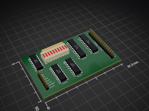
DutchMaker/TTL-computer
Building a computer from scratch using 74xx logic chips


DutchMaker/TTL-computer
Building a computer from scratch using 74xx logic chips


zynthian/zynthian-hw
Zynthian hardware stuff: PCBs, schemes, parts specifications, pin assignment, ...


Hack-a-Day/2025-Communicator_Badge
The 2025 Hackaday Supercon RF Communicator Badge


rheslip/2HPico-Eurorack-Module-Hardware
2HP Eurorack module based on Raspberry Pi Pico 2

mck1117/wideband
The firmware/boards directory contains configuration for each board this firmware supports.