2 layers75 × 23.9 mm
EEE3088F MHMZAM005 Sensing
Zamoe/EEE3088F-2024-VLLMUH015-MHMZAM005
GIt Repo for EEE3088F 2024 at UCT
43 partsGPL-3.0

 ductomn/Swarm-robot
Bachelor Thesis - Design and implementation of a cooperative robotic platform with simple communication
Board v1 is an open-source printed circuit board by ductomn, from the ductomn/Swarm-robot repository on GitHub. It is a 4-layer board of 50 × 50 mm with 79 parts on 65 nets, routed with 351 tracks and 61 vias.
It is built around the ESP32-WROOM-32UE-N4, MT3608 and AMS1117-3.3, with the TP4056, TEFT4300 and OED-EL-1L2 among its other parts. Its parts include 27 resistors, 11 capacitors, 10 transistors, 6 diodes and 4 ICs. It belongs with the ESP32 boards of this library.


A low-cost, scalable swarm robotic platform designed for research and educational purposes, capable of infrared (IR)-based communication and basic cooperative behaviors.
Playlist of videos showcasing robots and algorithms: https://www.youtube.com/playlist?list=PLNTM9zCJujTltedypfpow2rPiPkVAqfGI
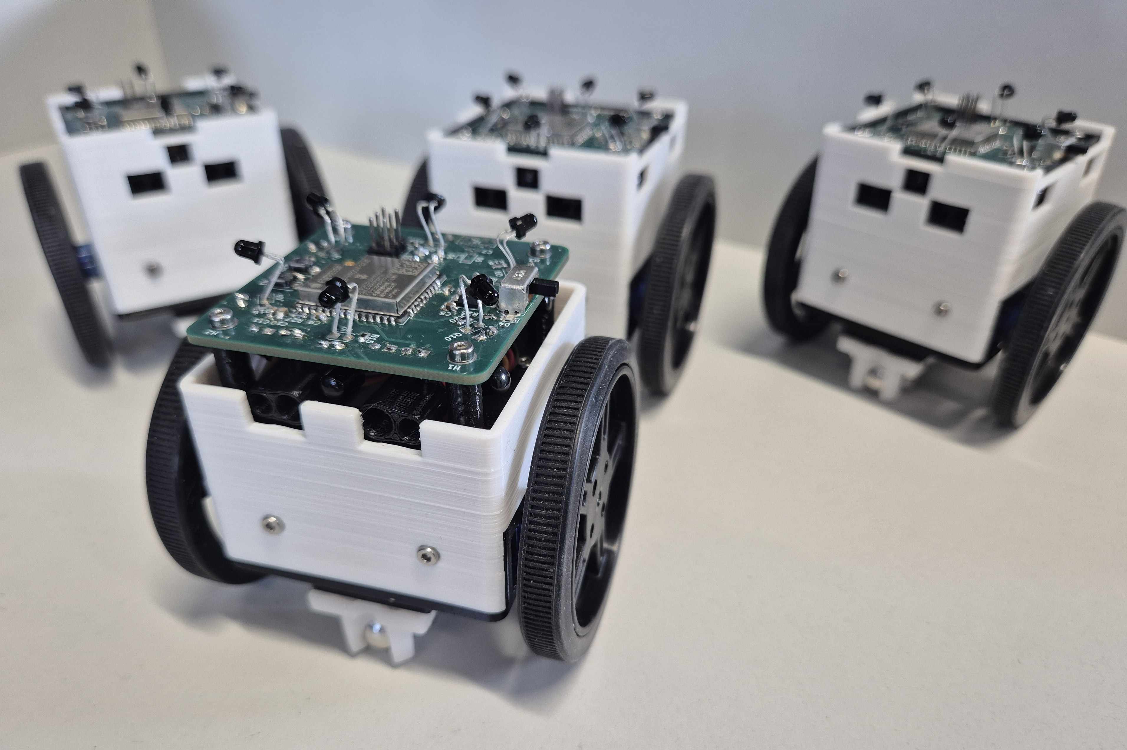
This project focuses on the design of a cooperative robotic platform built around the ESP32 microcontroller. The primary goal is to enable simple, local communication and decentralized coordination among identical robots, forming a swarm.
Key design constraints:
Thesis Title:
Návrh a realizace kooperativní robotické platformy s jednoduchou komunikací
(Design and Implementation of a Cooperative Robotic Platform with Simple Communication)
6 pairs of IR LEDs and phototransistors evenly placed around the robot enable full directional communication.
2 front-facing IR LED + phototransistor pairs detect obstacles.
Simulates a robot "calling" others to complete a task.
Modified CSMA/CA protocol ensures robots check for ongoing transmissions before broadcasting.
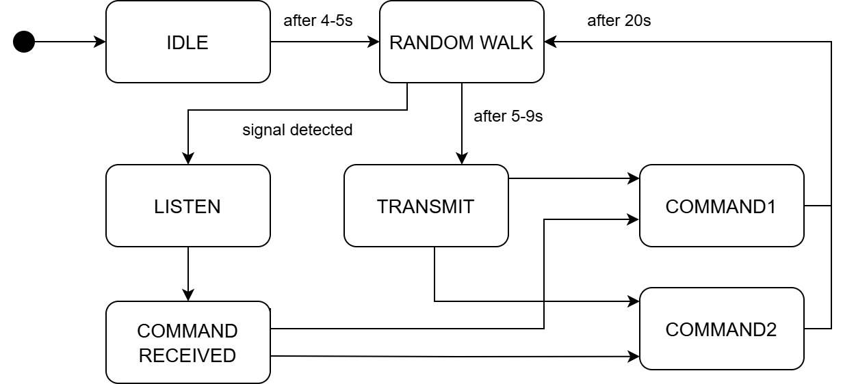
Robots walk randomly looking for signals:
Leader can be pre-set (WITH_LEADER 1)
Flowchart of system with leader:
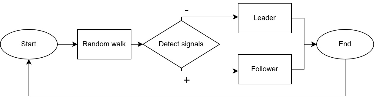
Implemented algorithms:
Follow
Followers track the leader, who moves randomly.
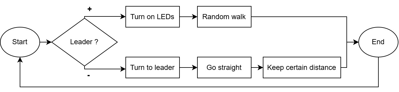
Spread Out
Leader stays in place and acts as a beacon. Followers spread and return.
No signal detection or leader election.
Algorithms run immediately after power-on.
Implemented algorithms:
Follow Chain
Robots follow each other in a line. First robot walks randomly. Predefined or dynamic ID (order) assignment.

Chain
Robots stay still in a line. The last robot moves forward to the front.
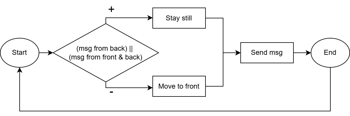
Each robot uses a finite state machine (FSM) for autonomous control and decision-making. The diagram shows the flow of states of algorithms with leader.
io_define – I/O pin mappings, robot IDservo_driver – movement (servo) controlled_driver – IR LED driverhwtimer – Hardware timer driveradc_lib – ADC driverdm_comm – IR communication (Manchester encoding, CSMA/CA)coop – Cooperative algorithm logicstate_machine – FSM and behavior transitionsESP32DOIT-DEVKIT-V1Movement Calibration
The robot doesn’t use encoders, so the motors may spin at different speeds, causing drift.
Adjust SERVO_FORWARD_LEFT_MOD and SERVO_BACKWARDS_RIGHT_MOD in io_define.h to straighten movement.
IR Signal Thresholds
Tune SIG_THRESHOLD in dm_comm.h and DIS_THRESHOLD in coop.h to adjust signal sensitivity.
Algorithm Selection
Some algorithms (like Chain or Follow Chain) should start immediately on power-up.
Define the startup behavior by setting flags to "1" (CHAIN or FOLLOW_CHAIN).
io_define.h and set:
ROBOT_ID – unique number per robotWITH_LEADER – 1 (for pre-set leader - ID1) or 0CHAIN or FOLLOW_CHAIN – chosen algorithm| Qty | Value | Footprint | References |
|---|---|---|---|
| 8 | 39 | Resistor_SMD:R_0603_1608Metric_Pad0.98x0.95mm_HandSolder | R3, R4, R7, R8, R9, R10, R11, R12 |
| 8 | 4k7 | Resistor_SMD:R_0603_1608Metric_Pad0.98x0.95mm_HandSolder | R1, R2, R15, R16, R17, R18, R19, R20 |
| 8 | TEFT4300 | LED_THT:LED_D1.8mm_W3.3mm_H2.4mm | Q1, Q2, Q5, Q6, Q7, Q8, Q9, Q10 |
| 6 | OED-EL-1L2 | LED_THT:LED_D1.8mm_W3.3mm_H2.4mm | IR3, IR4, IR5, IR6, IR7, IR8 |
| 4 | 0.1uF | Capacitor_SMD:C_0603_1608Metric_Pad1.08x0.95mm_HandSolder | C7, C8, C9, C11 |
| 4 | MountingHole_Pad | MountingHole:MountingHole_2.2mm_M2_Pad | H1, H2, H3, H4 |
| 2 | 100 | Resistor_SMD:R_0603_1608Metric_Pad0.98x0.95mm_HandSolder | R5, R13 |
| 2 | 10uF | Capacitor_SMD:C_1210_3225Metric_Pad1.33x2.70mm_HandSolder | C3, C4 |
| 2 | 10uF | Capacitor_SMD:C_0603_1608Metric_Pad1.08x0.95mm_HandSolder | C5, C6 |
| 2 | 1k | Resistor_SMD:R_0603_1608Metric_Pad0.98x0.95mm_HandSolder | R24, R25 |
| 2 | 22uF | Capacitor_SMD:C_1210_3225Metric_Pad1.33x2.70mm_HandSolder | C1, C2 |
| 2 | 47k | Resistor_SMD:R_0603_1608Metric_Pad0.98x0.95mm_HandSolder | R6, R14 |
| 2 | SFH4544 | LED_THT:LED_D1.8mm_W3.3mm_H2.4mm | IR1, IR2 |
| 2 | SG90 | Connector_PinHeader_2.54mm:PinHeader_1x03_P2.54mm_Vertical | M1, M2 |
| 2 | SI2312CDS | Package_TO_SOT_SMD:SOT-23 | Q3, Q4 |
| 2 | TS-1088R-02026 | 0_Custom_Footprints:SW_Tactile_TS-1088R-02026 | BOOT, EN |
| 1 | 10k | Resistor_SMD:R_0603_1608Metric_Pad0.98x0.95mm_HandSolder | R27 |
| 1 | 16k | Resistor_SMD:R_0603_1608Metric_Pad0.98x0.95mm_HandSolder | R21 |
| 1 | 1N5819HW-7-F | Diode_SMD:D_SOD-123 | D5 |
| 1 | 1k2 | Resistor_SMD:R_0603_1608Metric_Pad0.98x0.95mm_HandSolder | R23 |
| 1 | 22uF | Capacitor_SMD:C_0603_1608Metric_Pad1.08x0.95mm_HandSolder | C10 |
| 1 | 2k2 | Resistor_SMD:R_0603_1608Metric_Pad0.98x0.95mm_HandSolder | R22 |
| 1 | 4.7uH | Inductor_SMD:L_Chilisin_BMRx00060630 | L1 |
| 1 | 5k1 | Resistor_SMD:R_0603_1608Metric_Pad0.98x0.95mm_HandSolder | R26 |
| 1 | AMS1117-3.3 | Package_TO_SOT_SMD:SOT-223-3_TabPin2 | U3 |
| 1 | D_Schottky | Diode_SMD:D_SMC | D1 |
| 1 | ESD5Z5.0T1G | Diode_SMD:D_SOD-523 | D6 |
| 1 | ESP32-WROOM-32UE | RF_Module:ESP32-WROOM-32UE | U4 |
| 1 | LED | LED_SMD:LED_0603_1608Metric_Pad1.05x0.95mm_HandSolder | D4 |
| 1 | LED_GREEN | LED_SMD:LED_0603_1608Metric_Pad1.05x0.95mm_HandSolder | D3 |
| 1 | LED_RED | LED_SMD:LED_0603_1608Metric_Pad1.05x0.95mm_HandSolder | D2 |
| 1 | Li-Po 3.7V | Connector_JST:JST_PH_S2B-PH-SM4-TB_1x02-1MP_P2.00mm_Horizontal | J1 |
| 1 | MT3608 | Package_TO_SOT_SMD:SOT-23-6 | U1 |
| 1 | SLW-864574-5A-RA-N-D | Button_Switch_THT:SW_Slide_SPDT_Straight_CK_OS102011MS2Q | SW1 |
| 1 | TP4056 | Package_SO:SOP-8_3.9x4.9mm_P1.27mm | U2 |
| 1 | USB_B_Micro | Connector_USB:USB_Micro-B_Amphenol_10118194_Horizontal | J2 |
| 1 | ~ | Connector_PinHeader_2.54mm:PinHeader_2x03_P2.54mm_Vertical | Comms1 |
It measures 50 × 50 mm and has 4 copper layers, 1.6 mm thick.
79 parts, built around the ESP32-WROOM-32UE-N4, MT3608, AMS1117-3.3 and TP4056. The full list of its parts is on this page, with links to each part's symbol and footprint where PCBKit's library has them.
From the ductomn/Swarm-robot repository on GitHub, at the commit this page was made from: the board is PCB/DPS/Board_v1/Board/Board.kicad_pcb and its schematic PCB/DPS/Board_v1/Board/Board.kicad_sch. PCBKit opens the board in the browser, with nothing to install.
Its repository states no licence, so its author keeps all rights: ask ductomn before reusing the design.
Zamoe/EEE3088F-2024-VLLMUH015-MHMZAM005
GIt Repo for EEE3088F 2024 at UCT

RoboticsBrno/Robutek
Robůtek je robotická platforma založená na čipu ESP32-S3. Je velice rozšitiřelný, ale ze základu umí jezdit, kreslit fixou, jezdit po čáře, pohybovat se bludištěm. Programování je přes Jaculus.

filmolino/SlideScanner
The Filmolino SlideScanner is a device that makes it easy to scan slides in magazines fully automated using a modified slide projector and a digital camera.

PerMalmberg/IO-Card-G3
This is my custom I/O card, third generation. Main purpose is to serve as an alarm system.

rossuthoff/multichannel_led_driver
LED driver for up to nine LED strings


mirobotech/CHRP400
CHRP4 (Common Hardware Robotics Project 4, rev. 0) KiCad schematic and PCB design files.
