2 layers40.9 × 85 mm
Studio mic
Spirit532/studio_mic
A simple, easy to build preamplifier for any true condenser capsule, to make a condenser microphone
63 parts150MIT

 ds-kiel/grace
GRACE: GPIO tracing for distributed IoT testbeds
Cc1101-expansion board is an open-source printed circuit board by ds-kiel, from the ds-kiel/grace repository on GitHub. It is a 2-layer board of 65 × 56 mm with 8 parts on 41 nets, routed with 81 tracks and 2 vias.
It is built around the M2.5.
This simple PCB can be used to wire together the development boards for easier deployment. Alternatively, one can simply wire together everything using jumper wires. We produced our PCBs at JLCPCB, look below for our order configuration. The schematic files can be opened and exported to gerber files using KiCad. You can also look at the schematic for a reference as to how to wire everything together.
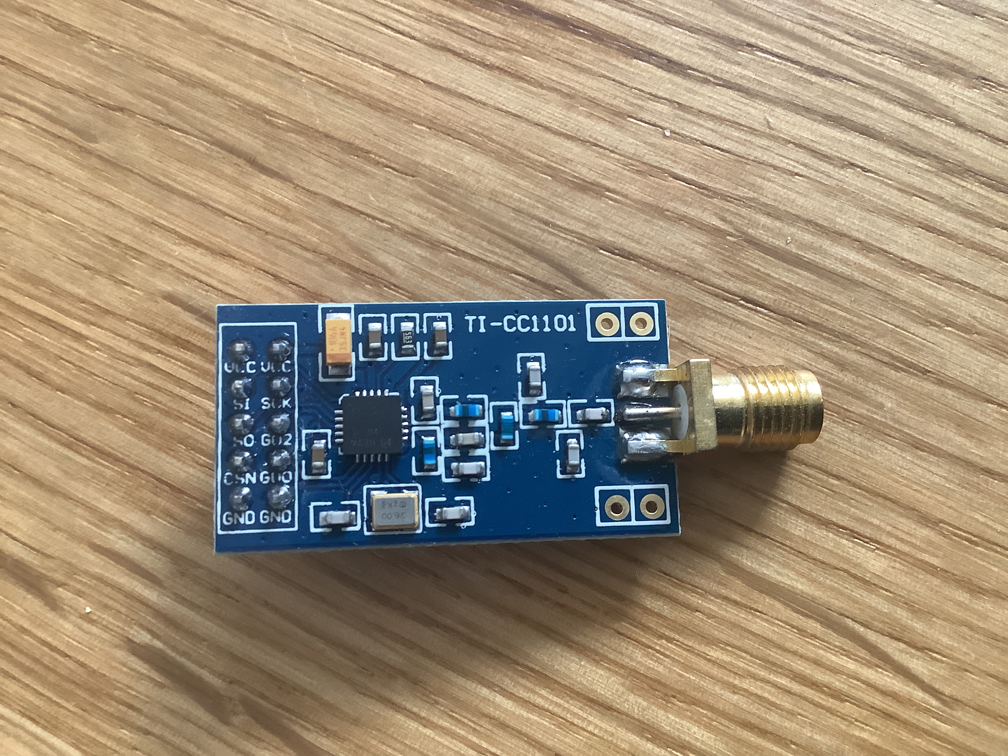
We use a commonly available of-the-shelf cc1101 development board for our setup. If you want to use our circuit board for deployment, you need to get a board with the same pin-out configuration. If you don't want to use our board and use jumper wires instead, you can get one of the other commonly available development boards. Just make sure that at least one GPIO (GDx) is exposed.
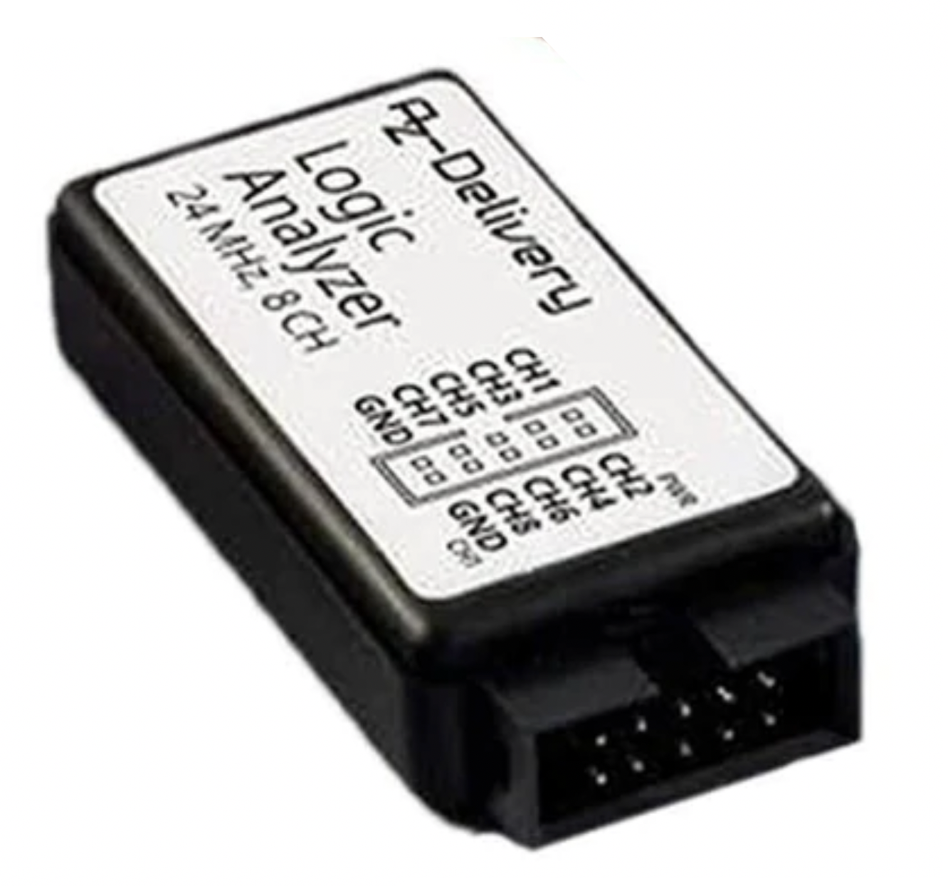
Use one of the commonly available ez-usb fx2lp based logic analyzer if you want to use our PCB. Otherwise, if you jump wire everything you can also use a fx2lp development board.
We need one node that emits a reference message every other second. For our setup, we use a STM32F401CC, but other microcontrollers can easily be adapted to work as reference node as well.
| Qty | Value | Footprint | References |
|---|---|---|---|
| 4 | M2.5 | MountingHole:MountingHole_2.7mm_M2.5 | MK1, MK2, MK3, MK4 |
| 2 | Conn_02x05_Odd_Even | Connector_PinHeader_2.54mm:PinHeader_2x05_P2.54mm_Vertical | J1, J2 |
| 1 | Conn_01x08 | Connector_PinHeader_2.54mm:PinHeader_1x08_P2.54mm_Horizontal | J3 |
| 1 | Conn_02x20_Odd_Even | Connector_PinSocket_2.54mm:PinSocket_2x20_P2.54mm_Vertical | P1 |
It measures 65 × 56 mm and has 2 copper layers, 1.6 mm thick.
8 parts, built around the M2.5. The full list of its parts is on this page, with links to each part's symbol and footprint where PCBKit's library has them.
From the ds-kiel/grace repository on GitHub, at the commit this page was made from: the board is raspi/gpio-tracer/hardware/cc1101-expansion-board.kicad_pcb. PCBKit opens the board in the browser, with nothing to install.
Its repository states no licence, so its author keeps all rights: ask ds-kiel before reusing the design.
Spirit532/studio_mic
A simple, easy to build preamplifier for any true condenser capsule, to make a condenser microphone


gmcn42/clumsyMIDI
A THT-only Raspberry Pi expansion board containing a MIDI interface, DAC, and OLED display

DvidMakesThings/HW_PDNode-600-Pro
The PDNode-600 is a professional-grade, 600W USB Power Delivery Unit designed specifically for compact 10-inch rack systems, targeting embedded developers, homelab enthusiasts, test benches, and smart infrastructure.


Zebra-Rodeo/marelleo
Une boîte qui raconte une histoire quand on pose une figurine dessus. Boîtier, carte, micrologiciel et doc pour la refaire.

dsanchezseco/punk75
Ortholinear keyboard with 75 keys and all components through hole