
2 layers100 × 100 mm
CNC Control Panel
comakingspace/Parts
All upgrade/replacement part files for our machines and tools.
50 parts2
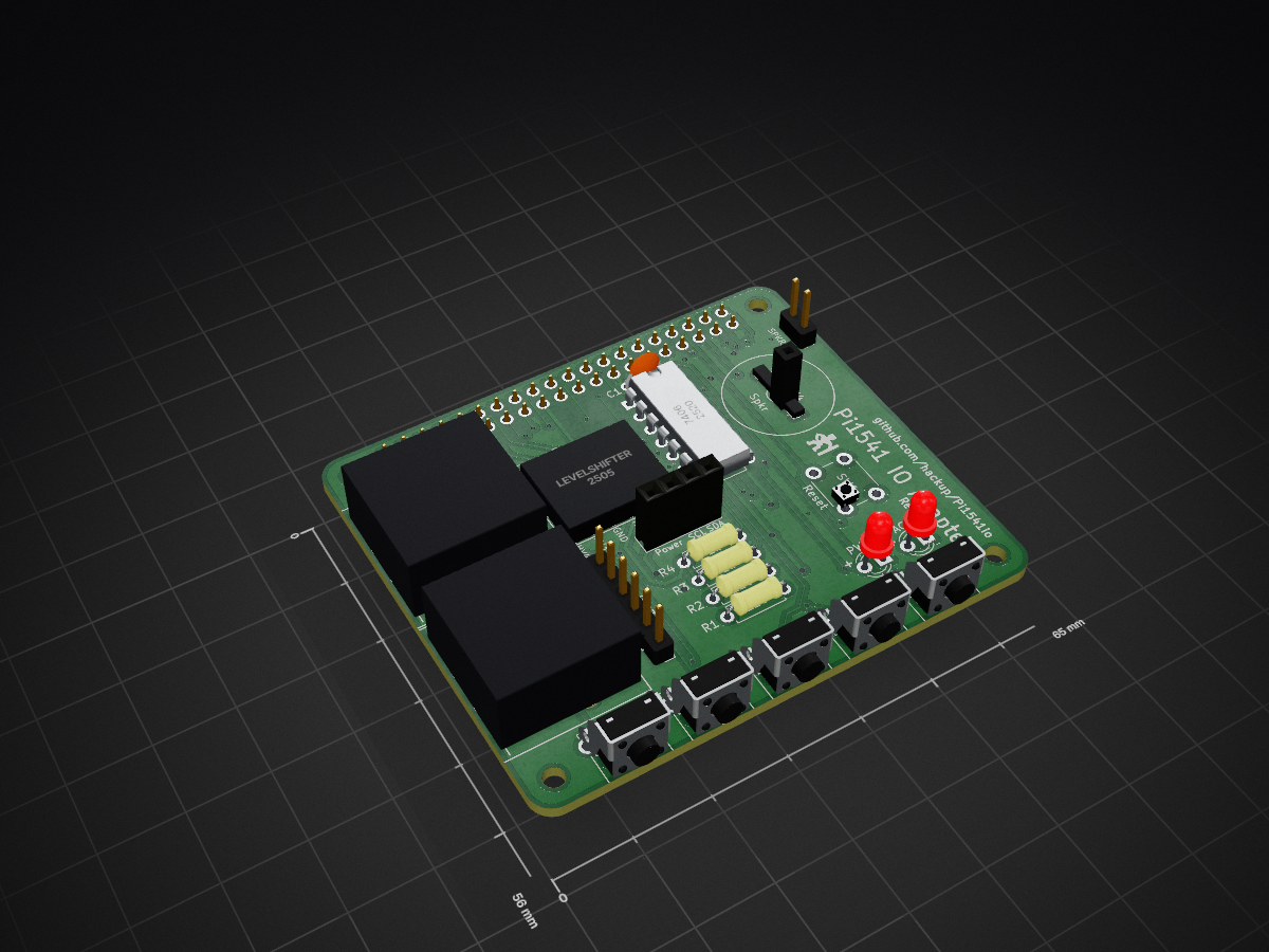
 hackup/Pi1541io109
Raspberry Pi extension board for the PI1541 project.
Pi1541io is an open-source printed circuit board by hackup, from the hackup/Pi1541io repository on GitHub, published under the CC-BY-SA-4.0 licence. It is a 2-layer board of 65 × 56 mm with 57 parts on 41 nets, routed with 549 tracks and 66 vias.
It is built around the BSS138 and M2.5. Its parts include 17 connectors, 15 resistors, 7 switches, 5 transistors and 2 ICs. It belongs with the retro computing and games boards of this library.
This is an IO adapter board for the Raspberry Pi 3, based on the awesome Pi1541 project by Steve White. It is currently very much work in progress. USE AT YOUR OWN RISK!
Details of the adapter board development are documented on hackup.net. The Gerber files for the latest stable revision are included in the repository. Also, the boards are ready to be ordered directly from PCBWay or DirtyPCBs.
This revision of the board resolves the I2C power supply issues of the previous version. All relevant aspects of the I2C header must now be configured using solder bridges on the bottom side of the PCB.
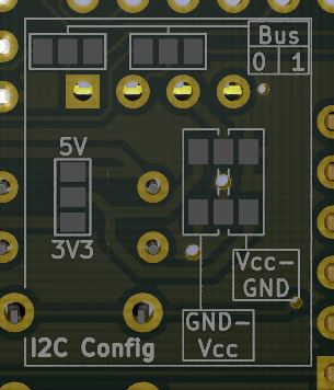
See here for more details.
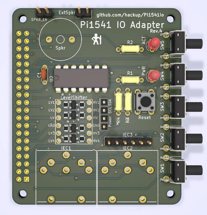
The third revision features an I2C header for connecting a SSD1306 based OLED display module. The power line on this header is connected to 5V of the Raspberry. This is the preferred option for display modules that bring their own 3.3V regulator. Unfortunately, there seem to be modules out there without such a regulator. Connecting one of those to 5V will damage both the display and the Raspberry.
This issue is resolved in revision 4. So, unless you already have one of these boards you better skip directly to revision 4.
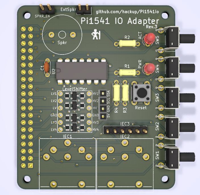
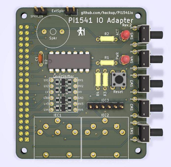
The second revision features quite a few improvements, the most important one being optional support for the 7406 bus driver IC. For further details and instructions on how to assemble this board see here.
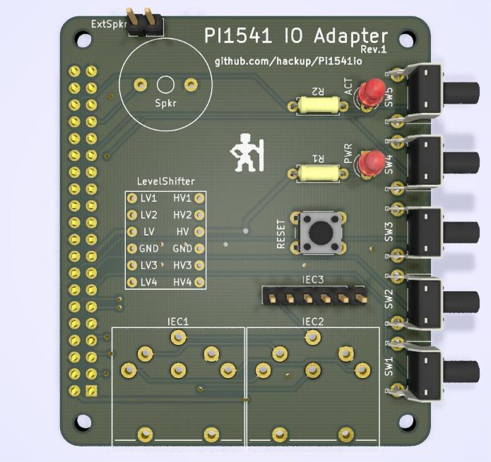
A prototype batch of the first revision has been manufactured and tested. It is generally working but there are a few minor issues. The Gerber files for this revision are included, but I would currently recommend waiting for revision 2.
 This work is licensed under a
Creative Commons Attribution-ShareAlike 4.0 International License
| Qty | Value | Footprint | References |
|---|---|---|---|
| 10 | 10k | Resistors_SMD:R_0805 | R5, R6, R7, R8, R9, R10, R11, R12, R14, R15 |
| 5 | BSS138 | TO_SOT_Packages_SMD:SOT-23 | Q1, Q2, Q3, Q4, Q5 |
| 5 | GS3 | Connectors:GS3 | J5, J6, J7, J8, J9 |
| 5 | SW_Push | Buttons_Switches_THT:SW_Tactile_SPST_Angled_PTS645Vx83-2LFS | SW1, SW2, SW3, SW4, SW5 |
| 4 | M2.5 | Mounting_Holes:MountingHole_2.5mm | MK1, MK2, MK3, MK4 |
| 4 | SDA | Connectors:GS3 | J10, J13, J14, J15 |
| 2 | 1k | Resistors_THT:R_Axial_DIN0207_L6.3mm_D2.5mm_P7.62mm_Horizontal | R3, R4 |
| 2 | 220 | Resistors_THT:R_Axial_DIN0207_L6.3mm_D2.5mm_P7.62mm_Horizontal | R1, R2 |
| 2 | ZipTie | DIN-Connector:ZipTie_3.0mm | MK5, MK6 |
| 1 | 100n | Capacitors_THT:C_Disc_D4.3mm_W1.9mm_P5.00mm | C1 |
| 1 | 1k | Resistors_SMD:R_0805_HandSoldering | R13 |
| 1 | 7406 | Housings_DIP:DIP-14_W7.62mm | U2 |
| 1 | ACT | LEDs:LED_D3.0mm | D2 |
| 1 | Conn_02x20_Odd_Even | Socket_Strips:Socket_Strip_Straight_2x20_Pitch2.54mm | P1 |
| 1 | ExtSpkr | Pin_Headers:Pin_Header_Straight_1x01_Pitch2.54mm | J4 |
| 1 | GS2 | Connectors:GS2 | J16 |
| 1 | I2C | Socket_Strips:Socket_Strip_Straight_1x04_Pitch2.54mm | J12 |
| 1 | IEC1 | DIN-Connector:DIN-6-Variable | J1 |
| 1 | IEC2 | DIN-Connector:DIN-6-Variable | J2 |
| 1 | IEC3 | Pin_Headers:Pin_Header_Straight_1x06_Pitch2.54mm | J3 |
| 1 | LOGO | Logo:bigby2 | G*** |
| 1 | LevelShifter | hackup:LevelShifterModule4CH | U1 |
| 1 | PWR | LEDs:LED_D3.0mm | D1 |
| 1 | Reset | Buttons_Switches_THT:SW_PUSH_6mm | SW6 |
| 1 | SCL | Connectors:GS3 | J11 |
| 1 | SPKR_EN | Pin_Headers:Pin_Header_Straight_2x01_Pitch2.54mm | SW7 |
| 1 | Spkr | hackup:Piezo Speaker 1407 | LS1 |
It measures 65 × 56 mm and has 2 copper layers, 1.6 mm thick.
57 parts, built around the BSS138 and M2.5. The full list of its parts is on this page, with links to each part's symbol and footprint where PCBKit's library has them.
From the hackup/Pi1541io repository on GitHub, at the commit this page was made from: the board is Pi1541io.kicad_pcb. PCBKit opens the board in the browser, with nothing to install.
Its repository publishes it under the CC-BY-SA-4.0 licence: you may reuse it on that licence's terms (keep the author's notice, and for a copyleft licence share your changes alike).
comakingspace/Parts
All upgrade/replacement part files for our machines and tools.

erinjense/raspberrypi-indoor-air-quality-pcb
Hardware and Software for a Indoor Air Quality Logger


netz39/rollladensteuerung
Schaltpläne, Layouts und Firmware für Schließanlage und Rollladensteuerung

NilsEngelbach/air-quality-pcb
Seventh iteration: ESP8266 → ESP32-C3 (native USB, no UART bridge), fixes from the v6 design review, right-angle switches with longer actuators, a STEMMA QT port for optional sensors, and charge-status sensing.

PimentoFr/plant-monitor
Developpement d'un capteur de potager indoor/outdoorn solaire et connecté via Sigfox

winson3QQ/Batman
Home project for Halow+openMANET on Pi4 & & Seeed WM1302 HAT & Wio-WM6108

xmyoot/cellular-epaper-esp32s3-sim7600
Low-Power Cellular ePaper Device with ESP32-S3 and SIM7600 LTE Cat-1