2 layers315 × 121 mm

 draarivpatel-ui/hackpad
AarivPad: 3x3 mechanical macropad with EC11 rotary encoder, 128x32 OLED, SK6812 RGB underglow, KiCad 8 PCB, OpenSCAD case, and KMK firmware
Aarivpad is an open-source printed circuit board by draarivpatel-ui, from the draarivpatel-ui/hackpad repository on GitHub, published under the MIT licence. It is a 2-layer board of 68 × 84 mm with 29 parts on 27 nets, routed with 30 tracks and 0 vias.
It is built around the 1N4148W and SK6812. Its parts include 13 diodes, 10 switches and 2 ICs. It belongs with the keyboards and input and lEDs and displays boards and the RP2040 boards of this library.


Try the Live Interactive 3D Hardware Workbench & KMK Simulator: https://aariv.me/hackpad/
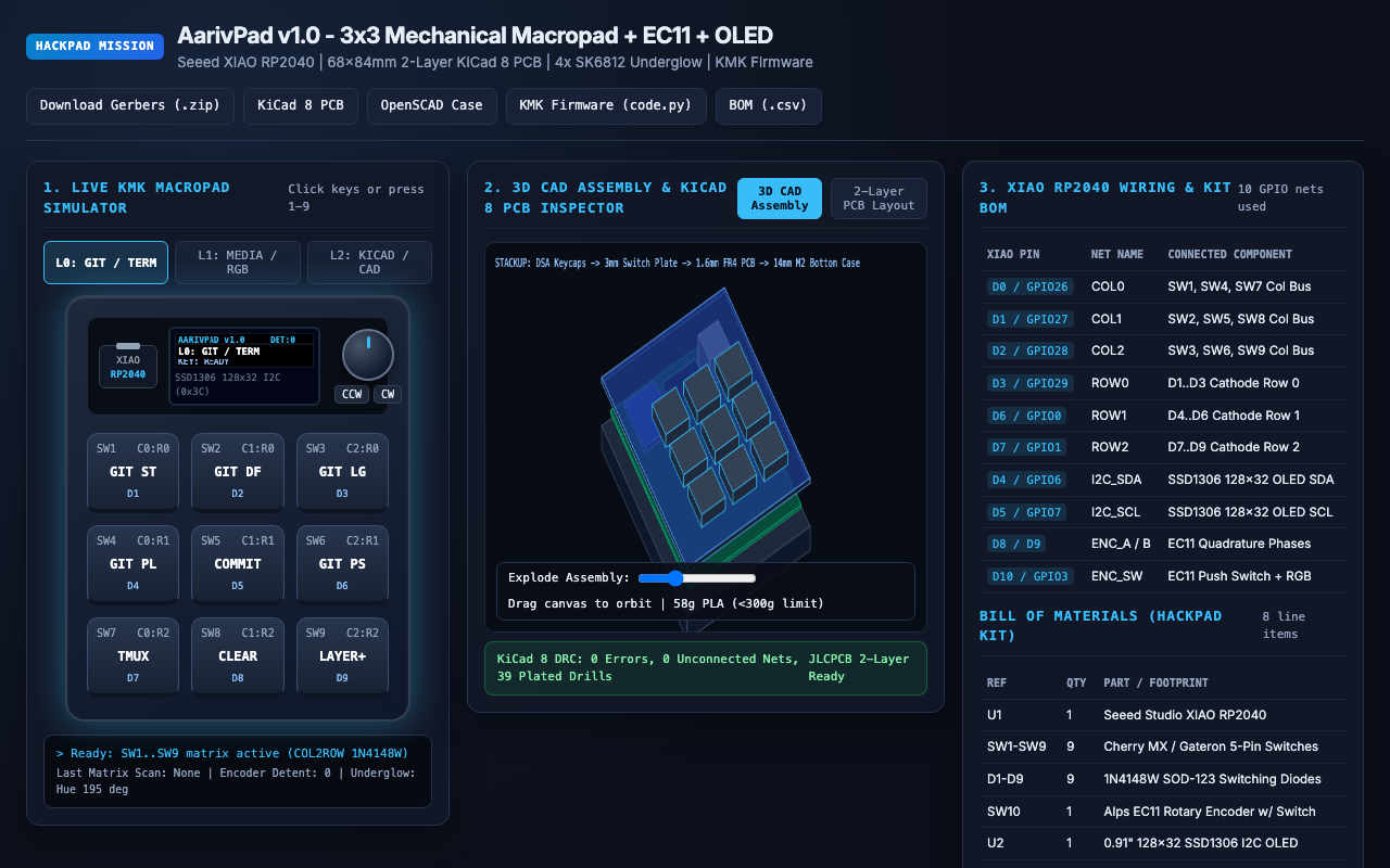
I designed and built AarivPad for the Hack Club Stardance Hackpad mission. It is a custom 3x3 mechanical macropad powered by a Seeed Studio XIAO RP2040, an Alps EC11 rotary encoder with push-button switch, a 0.91" 128x32 SSD1306 I2C OLED status display, and four SK6812 MINI-E reverse-mount addressable RGB underglow LEDs.
Alongside the complete KiCad 8 schematic, 2-layer routed PCB, JLCPCB Gerber archive, parametric OpenSCAD enclosure STLs, and CircuitPython KMK firmware, I also built an interactive browser workbench at https://aariv.me/hackpad/ so you can test all 9 keys across all 3 macro layers, spin the EC11 encoder, inspect the 2-layer copper traces, and orbit the exploded 3D CAD assembly directly in your browser.
Whenever I am working across terminal Git sessions, KiCad PCB layout, and media playback, I constantly find myself reaching for awkward multi-finger keyboard chords (git status, git diff --stat, git log --oneline -n 15, switching tmux panes, or toggling KiCad copper layers and track widths).
I wanted a compact desk companion that sits right next to my mouse and gives me:
19.05mm (0.75") 3x3 grid for single-press macros.L0: GIT/DEV, L1: MEDIA/RGB, or L2: KICAD/CAD) is currently active.Because the Seeed Studio XIAO RP2040 exposes exactly 11 user GPIO pins (D0 through D10), fitting 9 switches, a quadrature rotary encoder + push button, an I2C OLED display, and an addressable RGB LED chain required careful pin budgeting:
COL0..COL2): Wired to D0 (GPIO26), D1 (GPIO27), and D2 (GPIO28).ROW0..ROW2): Wired to D3 (GPIO29), D6 (GPIO0), and D7 (GPIO1) through nine 1N4148W SOD-123 switching diodes (D1..D9) oriented COL2ROW so pressing any combination of keys simultaneously never causes ghosting.SDA / SCL): Reserved D4 (GPIO6) and D5 (GPIO7) for the 0.91" 128x32 SSD1306 OLED display at address 0x3C.ENC_A and ENC_B connect to D8 (GPIO2) and D9 (GPIO4), while D10 (GPIO3) handles the encoder push switch (ENC_SW) and drives the 4-pixel SK6812 MINI-E RGB underglow chain.firmware/code.py)I wrote the firmware in CircuitPython using KMK (kmk_keyboard, Layers, EncoderHandler, RGB, and adafruit_displayio_ssd1306):
GIT / TERMINAL): Single-key macros for git status -sb, git diff --stat, git add -A && git commit, git log --oneline -n 12, git pull --rebase, git push, tmux pane split, terminal clear, and layer cycle (DF(1)). Rotary dial scrolls terminal history line by line.MEDIA / RGB): Play/Pause, Next/Previous Track, Mute, RGB Hue/Animation toggle, Brightness step, and Window Snap shortcuts. Rotary dial controls system volume (VOL+ / VOL-).KICAD / CAD): KiCad track routing (X), via placement (V), copper layer flip (F.Cu <-> B.Cu), DRC inspector, 3D viewer launch (Alt+3), and measurement tool. Rotary dial zooms the canvas in and out.pcb/aarivpad.kicad_pcb): Routed on a compact 68.0mm x 84.0mm two-layer board with 1.6mm FR4 thickness, rounded 3.0mm corners, four M2 mounting holes (4.0mm inset), 0.25mm signal traces (0.50mm power rails), and stitched GND copper pours on both F.Cu and B.Cu.cad/aarivpad_case.scad): Includes a heat-set M2 bottom tray (bottom_case.stl), a 1.5mm/3.0mm clip-in MX switch plate (switch_plate.stl) with a framed viewport over the OLED and clearance for the EC11 bushing, and a knurled 6.0mm D-shaft knob (encoder_knob.stl). Total print weight is ~58g PLA - well under the 300g Printing Legion limit.9 (switches) + 2 (I2C) + 3 (encoder) + 1 (RGB) = 15 GPIOs, which exceeds the XIAO RP2040's 11 pins. Scanning the 9 switches as a 3x3 diode matrix reduced the switches from 9 pins down to 6 (3 cols + 3 rows), leaving D4/D5 free for hardware I2C and D8/D9/D10 free for the EC11 encoder and RGB chain.68mm x 84mm board, placing the XIAO RP2040, the 0.91" OLED module, and the EC11 rotary encoder along the top header zone required carefully offsetting the OLED center to (22.0mm, 14.5mm) and the EC11 shaft to (52.5mm, 14.5mm) so the top switch row (SW1..SW3 at Y = 34.0mm) clears both the OLED PCB edge and the 18mm knurled encoder knob with zero keycap rub.| Seeed XIAO RP2040 Pin | Net Name | Connected Hardware |
|---|---|---|
D0 / GPIO26 | COL0 | Column 0 Switch Bus (SW1, SW4, SW7) |
D1 / GPIO27 | COL1 | Column 1 Switch Bus (SW2, SW5, SW8) |
D2 / GPIO28 | COL2 | Column 2 Switch Bus (SW3, SW6, SW9) |
D3 / GPIO29 | ROW0 | Row 0 Diode Bus (D1, D2, D3 cathodes) |
D6 / GPIO0 | ROW1 | Row 1 Diode Bus (D4, D5, D6 cathodes) |
D7 / GPIO1 | ROW2 | Row 2 Diode Bus (D7, D8, D9 cathodes) |
D4 / GPIO6 (SDA) | I2C_SDA | 0.91" 128x32 SSD1306 OLED Display (SDA) |
D5 / GPIO7 (SCL) | I2C_SCL | 0.91" 128x32 SSD1306 OLED Display (SCL) |
D8 / GPIO2 | ENC_A | EC11 Rotary Encoder Phase A |
D9 / GPIO4 | ENC_B | EC11 Rotary Encoder Phase B |
D10 / GPIO3 | ENC_SW | EC11 Push Switch + SK6812 RGB Underglow Chain |
3V3 / 5V / GND | Power | OLED VCC (3V3), SK6812 VDD (5V), Common Ground |
| Ref | Qty | Component | Footprint / Package |
|---|---|---|---|
U1 | 1 | Seeed Studio XIAO RP2040 | Through-hole / SMD 14-pin Module |
SW1-SW9 | 9 | Cherry MX / Gateron 5-Pin Mechanical Switches | SW_Cherry_MX_1.00u_PCB |
D1-D9 | 9 | 1N4148W / 1N4148 Switching Diodes | D_SOD-123 (THT compatible pads) |
SW10 | 1 | Alps EC11 Rotary Encoder with Push Switch | RotaryEncoder_Alps_EC11E-Switch |
U2 | 1 | 0.91" 128x32 SSD1306 I2C OLED Display | 4-Pin 2.54mm Header (GND/VCC/SCL/SDA) |
LED1-LED4 | 4 | SK6812 MINI-E Addressable RGB LEDs | Reverse-Mount PLCC4 3.2x2.8mm |
K1-K9 | 9 | 1u Blank DSA PBT Keycaps | Standard MX Stem |
H1-H4 | 4 | M2x8mm Screws + M2x5mm Brass Heat-Set Inserts | 2.2mm Mounting Holes |
index.html locally) to test the 9-key KMK macro simulator with Web Audio mechanical switch clicks, rotate the EC11 encoder, inspect the 2-layer PCB traces (F.Cu, B.Cu, F.SilkS), and orbit the 3D exploded CAD assembly.pcb/aarivpad.kicad_pro in KiCad 8 to inspect the schematic (pcb/aarivpad.kicad_sch) and routed PCB (pcb/aarivpad.kicad_pcb). Fabrication-ready Gerbers are zipped at pcb/gerbers/aarivpad-gerbers.zip.cad/aarivpad_case.scad in OpenSCAD or slice cad/bottom_case.stl, cad/switch_plate.stl, and cad/encoder_knob.stl directly in Bambu Studio / PrusaSlicer.firmware/code.py onto your XIAO RP2040's CIRCUITPY drive with the kmk and adafruit_displayio_ssd1306 libraries installed.MIT.
| Qty | Value | Footprint | References |
|---|---|---|---|
| 9 | 1N4148W | Diode_SMD:D_SOD-123 | D1, D2, D3, D4, D5, D6, D7, D8, D9 |
| 4 | M2 | MountingHole:MountingHole_2.2mm_M2_Pad_Via | H1, H2, H3, H4 |
| 4 | SK6812 | LED_SMD:LED_SK6812MINI-E_PLCC4_3.2x2.8mm | LED1, LED2, LED3, LED4 |
| 1 | EC11 | Rotary_Encoder:RotaryEncoder_Alps_EC11E-Switch_Vertical_H20mm | SW10 |
| 1 | MX_K1 | Button_Switch_Keyboard:SW_Cherry_MX_1.00u_PCB | SW1 |
| 1 | MX_K2 | Button_Switch_Keyboard:SW_Cherry_MX_1.00u_PCB | SW2 |
| 1 | MX_K3 | Button_Switch_Keyboard:SW_Cherry_MX_1.00u_PCB | SW3 |
| 1 | MX_K4 | Button_Switch_Keyboard:SW_Cherry_MX_1.00u_PCB | SW4 |
| 1 | MX_K5 | Button_Switch_Keyboard:SW_Cherry_MX_1.00u_PCB | SW5 |
| 1 | MX_K6 | Button_Switch_Keyboard:SW_Cherry_MX_1.00u_PCB | SW6 |
| 1 | MX_K7 | Button_Switch_Keyboard:SW_Cherry_MX_1.00u_PCB | SW7 |
| 1 | MX_K8 | Button_Switch_Keyboard:SW_Cherry_MX_1.00u_PCB | SW8 |
| 1 | MX_K9 | Button_Switch_Keyboard:SW_Cherry_MX_1.00u_PCB | SW9 |
| 1 | OLED_128x32 | Display_OLED:SSD1306_128x32_0.91 | U2 |
| 1 | Seeed_XIAO_RP2040 | Module:Seeed_XIAO_RP2040_THT | U1 |
It measures 68 × 84 mm and has 2 copper layers, 1.6 mm thick.
29 parts, built around the 1N4148W and SK6812. The full list of its parts is on this page, with links to each part's symbol and footprint where PCBKit's library has them.
From the draarivpatel-ui/hackpad repository on GitHub, at the commit this page was made from: the board is pcb/aarivpad.kicad_pcb and its schematic pcb/aarivpad.kicad_sch. PCBKit opens the board in the browser, with nothing to install.
Its repository publishes it under the MIT licence: you may reuse it on that licence's terms (keep the author's notice, and for a copyleft licence share your changes alike).

FrederikWolter/FireKey_Hardware
Student project to create a macro keyboard. This is the hardware part.

zeerolux/core-micro
A lighting controller, control surface with 5 faders and 2 encoders, a USB DMX interface, an ARTNET node, and a standalone DMX generator.


garikotanishant/Macrooopad
A 10 key, 2 rotary encoder, macropad designed and built by me

