2 layers59.1 × 76.2 mm
PaperBack Display
dqydj/PaperBack_EPaper_Display
Internet Connected or Standard Input EPaper Display
64 parts83MIT
 dqydj/PaperBack_EPaper_Display83
Internet Connected or Standard Input EPaper Display
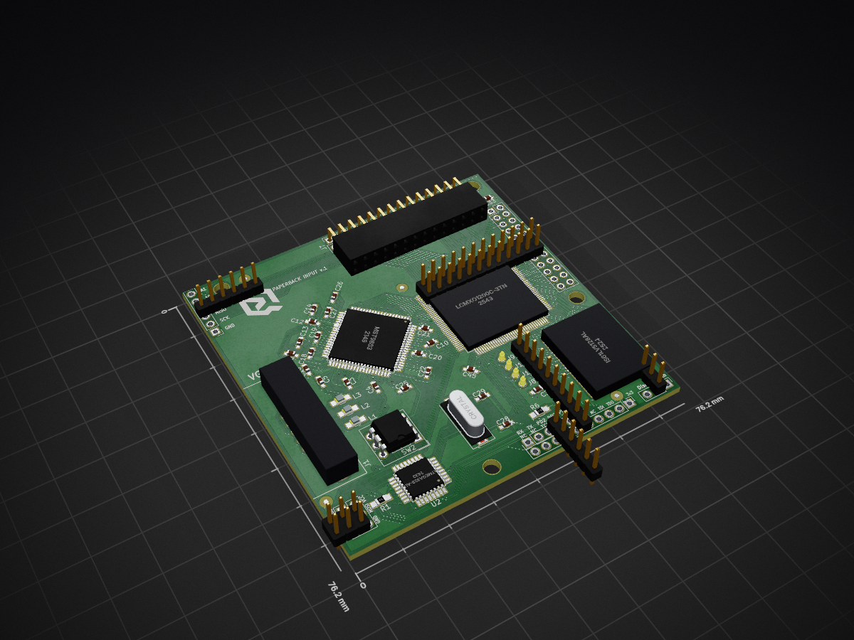
PaperBack Converter is an open-source printed circuit board by dqydj, from the dqydj/PaperBack_EPaper_Display repository on GitHub, published under the MIT licence. It is a 2-layer board of 76.2 × 76.2 mm with 92 parts on 156 nets, routed with 1,976 tracks and 118 vias.
It is built around the ATMEGA328-AU and LCMXO1200C-3TN144C. Its parts include 48 capacitors, 11 connectors, 10 resistors, 4 ICs and 3 inductors. It belongs with the lEDs and displays boards and the AVR (ATmega, ATtiny) and FPGA and CPLD boards of this library.


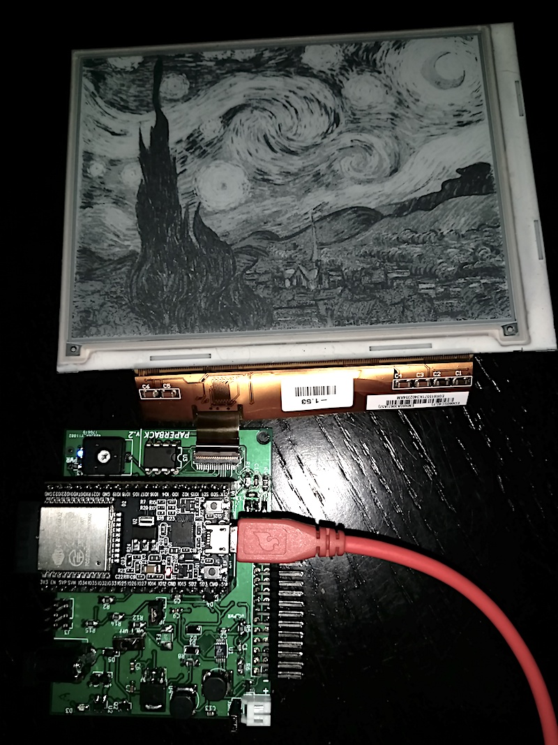
PaperBack is a modular, internet connected OR VGA EPaper Display. It consists of a breakout board for a 39 pin ePaper display and an ESP32 in one mode. In the other, remove the ESP32 and attach a VGA Conversion board and use regular VGA input to drive the display!
PaperBack is an entry in the 2017 Hackaday Prize, you can see a more complete (and verbose!) writeup here.
Currently, PaperBack works both driven by an ESP32 Development Board, or directly via VGA with the attached second PCB.
Hardware Overview:
Remember, choose one at a time! You can use the ESP32 breakout board with the ESP32 dev board, or remove the dev board and attach the VGA converter.
Unplug any ESP32 from the socket and attach both boards, then attach power (see below). When the board detects a signal it will start to refresh.
All firmware is in the /firmware_VGA/FPGA and /firmware_VGA/Microcontroller directories.
The user switches change color depth (read: shades of gray. 2 color is black & white.) and refresh speed: Switch 3 (Furthest from Microcontroller) Switch 2 Switch 1 (Closest to Microcontroller)
Remove the second PCB if attached, then add the ESP32. There are easy ways to add power (there are pins exposed too, but these are easiest). Unless using Lithium and the DC adapter, only use one at a time!
Demos:
convert.py in /software/image_converter automatically converts images which are compatible with Paperback's basic image demo. The image demo is in /firmware_ESP32/Paperback_Greyscale_Static_Image.| Qty | Value | Footprint | References |
|---|---|---|---|
| 39 | .1uF | Capacitors_SMD:C_0603_HandSoldering | C10, C11, C12, C13, C14, C15, C16, C17, C18, C19, C20, C21, C22, C23, C24, C25 +23 |
| 4 | 10k | Resistors_SMD:R_0805_HandSoldering | R1, R7, R8, R9 |
| 4 | TEST_1P | Measurement_Points:Measurement_Point_Round-SMD-Pad_Small | J8, J9, J10, J11 |
| 3 | 47nF | Capacitors_SMD:C_0603_HandSoldering | C3, C4, C5 |
| 3 | 75 | Resistors_SMD:R_0805_HandSoldering | R3, R4, R5 |
| 3 | FR_Bead | Inductors_SMD:L_0805_HandSoldering | L1, L2, L3 |
| 2 | 22pF | Capacitors_SMD:C_0603_HandSoldering | C28, C29 |
| 2 | 4.7uF | Capacitors_SMD:C_0603_HandSoldering | C33, C34 |
| 2 | CONN_01X06 | Pin_Headers:Pin_Header_Straight_1x06_Pitch2.54mm | J5, J6 |
| 1 | .0082uF | Capacitors_SMD:C_0603_HandSoldering | C1 |
| 1 | .082uF | Capacitors_SMD:C_0603_HandSoldering | C2 |
| 1 | 2.7k | Resistors_SMD:R_0805_HandSoldering | R2 |
| 1 | 20k | Resistors_SMD:R_0805_HandSoldering | R10 |
| 1 | 4.7K | Resistors_SMD:R_0805_HandSoldering | R6 |
| 1 | ATMEGA328-AU | Housings_QFP:TQFP-32_7x7mm_Pitch0.8mm | U2 |
| 1 | CONN_01X10 | Pin_Headers:Pin_Header_Straight_1x10_Pitch2.54mm | J3 |
| 1 | CONN_02X03 | Pin_Headers:Pin_Header_Straight_2x03_Pitch2.54mm | J2 |
| 1 | CONN_02X12 | Pin_Headers:Pin_Header_Straight_2x12_Pitch2.54mm | J4 |
| 1 | CONN_02X14 | Socket_Strips:Socket_Strip_Straight_2x14_Pitch2.54mm | J7 |
| 1 | Crystal | Crystals:Crystal_SMD_HC49-SD | Y1 |
| 1 | DB15_FEMALE_HighDensity | PK_Footprints:VGA_HD15 | J1 |
| 1 | DPDT | Pin_Headers:Pin_Header_Straight_1x03_Pitch2.54mm | SW1 |
| 1 | IS61LV5128AL | PK_Footprints:TSOP_II_44_0.8mm | U4 |
| 1 | LCMXO1200C-3TN144C | PK_Footprints:TQFP-144_20x20mm_Pitch0.5mm | U3 |
| 1 | LOGO | PK_Footprints:DQYDJ_LOGO_9_MM | G*** |
| 1 | LOGO | PK_Footprints:HaD_6mm | G*** |
| 1 | MST9883 | Housings_QFP:TQFP-80_14x14mm_Pitch0.65mm | U1 |
| 1 | SW_DIP_x03 | Buttons_Switches_THT:SW_DIP_x3_W7.62mm_Slide | SW2 |
The 81 most common of 92 parts.
dqydj/PaperBack_EPaper_Display
Internet Connected or Standard Input EPaper Display

famichu/MagLev_Switch_MX
The 3D printable magnetic levitation contactless switch with the linear output hall effect sensor.

etimou/arduino-pro-mini-kicad
This is a clone of the well known arduino board "pro-mini" designed in kicad while the original was designed in eagle. Ref https://store.arduino.cc/arduino-pro-mini

andykarpov/karabas-pro
FPGA based retrocomputer with FDD and HDD controllers


It measures 76.2 × 76.2 mm and has 2 copper layers, 1.6 mm thick.
92 parts, built around the ATMEGA328-AU and LCMXO1200C-3TN144C. The full list of its parts is on this page, with links to each part's symbol and footprint where PCBKit's library has them.
From the dqydj/PaperBack_EPaper_Display repository on GitHub, at the commit this page was made from: the board is hardware/PaperBack_Converter/PaperBack_Converter.kicad_pcb. PCBKit opens the board in the browser, with nothing to install.
Its repository publishes it under the MIT licence: you may reuse it on that licence's terms (keep the author's notice, and for a copyleft licence share your changes alike).