
4 layers99 × 53.3 mm
PSLab
fossasia/pslab-hardware
PSLab Hardware Design and Schematics https://pslab.io
199 parts1.7kApache-2.0

 Dpopa99/Electroboom
ECE411 Practicum Project
Osh park-2-layer kicad-5.99-drc template is an open-source printed circuit board by Dpopa99, from the Dpopa99/Electroboom repository on GitHub, published under the GPL-2.0 licence. It is a 2-layer board of 68.7 × 53.6 mm with 20 parts on 41 nets, routed with 102 tracks and 168 vias.
It is built around the 1N4148W. Its parts include 7 connectors, 4 resistors, 2 diodes and 1 switch.
Self defense is a necessity in our everyday lives. Whether you go on late night walks in downtown or spend your time in the rural side of town, you have to be prepared to defend yourself in a attack on your person. The stun gun in its mounted state creates a non-lethal electric shock used to stop an intruder from trespassing in an unauthorized area. The device is connected to an entrance door and upon activation of the device, any unauthorized operation of the door will send an electric shock from the device to the door thus immobilizing the assailant. Although they lack some advantages, such as the capacity to render an adversary helpless or a larger range, they are highly regarded for their ease of use and accessibility. The device is mounted, its size and weight make it portable and versatile. The overall product offers a sense of security and vigilance and should be marketed as such. The final marketing team should strongly consider any number of regulations as well as the variance in stand your ground laws within the U.S and internationally.
As a mounted device, it can be used by a vast number of customers such as small businesses owners, street food vendors, landlords, storage units owners, RV/Van campers, etc. to protect their belongings and themselves. Over the development of the product, it can be marketed to bigger businesses, corporate offices, banks, armored vehicles, private security firms, as well as in home security companies.
The competition can be felt through any of the manufacturers selling pre-installed security devices as well as products that offer multipurpose use such as the Ring Doorbell etc. Our product is in a completely different region as it targets a specific audience: the self-made individuals who are vigilant and don't hesitate to do what's necessary to protect what's theirs.
In comparison to other security devices and their features, our device can be priced within the $40-$50 range. There are several key factors that affect this price and as our design and overall ideas develop, the price may be adjusted accordingly. Factors like the mounting apparatus, 3D printed casing, any user interfaces used, and the cost of internal parts such as the transformer, connectors, and the PCB will eventually determine the final price for our product.
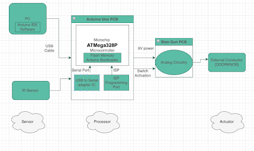
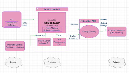
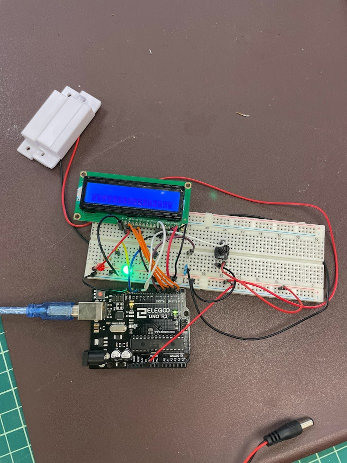
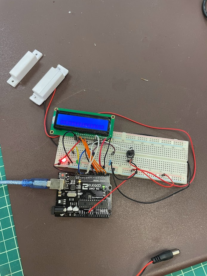
As seen from pictures above, the prototype is about finished and all that is needed to have a fully working prototype is the transformer (parts on their way). Image 1 shows the green LED on while the two door sensors are attached, this indicates that the system is armed and ready to go. In the second image, a red LED is shown, meaning that the door has been triggered and the voltage would be discharged out of the two open prongs that would be if the transformer parts were obtained. The video below shows the working prototype.
Current status 11/02/2022: We are awaiting the arrival of our 3.3V to 2000V transformer, upon arrival, we will assemble, test, and commit this transformer to our circuit. Along with this transformer, we will run tests to ensure that the voltage and current combinations will be safe for human contact, however, it is still reccomended that all testing be done by non-human contact, for the safety of our staff, faculty, and students.
GNU General Public License v2.0 The GNU GPL is the most widely used free software license and has a strong copyleft requirement. When distributing derived works, the source code of the work must be made available under the same license. There are multiple variants of the GNU GPL, each with different requirements.
See Documentation file in this repository for all sources used for this project
| Qty | Value | Footprint | References |
|---|---|---|---|
| 4 | MountingHole_3.2mm | Arduino_MountingHole:MountingHole_3.2mm | MH1, MH2, MH3, MH4 |
| 3 | 330 | Resistor_SMD:R_0805_2012Metric | R2, R3, R4 |
| 2 | Conn_01x02 | Connector_PinHeader_2.54mm:PinHeader_1x02_P2.54mm_Vertical | J5, J6 |
| 1 | 10K | Resistor_SMD:R_0805_2012Metric | R1 |
| 1 | 1N4148W | Diode_SMD:D_SOD-123 | D1 |
| 1 | Analog | Connector_PinSocket_2.54mm:PinSocket_1x06_P2.54mm_Vertical | J3 |
| 1 | Conn_01x16_Female | Connector_PinHeader_2.54mm:PinHeader_1x16_P2.54mm_Vertical | J7 |
| 1 | Digital/PWM | Connector_PinSocket_2.54mm:PinSocket_1x10_P2.54mm_Vertical | J2 |
| 1 | Digital/PWM | Connector_PinSocket_2.54mm:PinSocket_1x08_P2.54mm_Vertical | J4 |
| 1 | LED_BARG | LED_THT:LED_D5.0mm-4_RGB_Wide_Pins | D2 |
| 1 | LOGO | graphics:graphics2 | G*** |
| 1 | Power | Connector_PinSocket_2.54mm:PinSocket_1x08_P2.54mm_Vertical | J1 |
| 1 | R_Potentiometer | trimmer:TRIM_3362P-1-505LF | RV1 |
| 1 | SW_SPDT | slideswitch:EG1218 | SW1 |
It measures 68.7 × 53.6 mm and has 2 copper layers, 1.6 mm thick.
20 parts, built around the 1N4148W. The full list of its parts is on this page, with links to each part's symbol and footprint where PCBKit's library has them.
From the Dpopa99/Electroboom repository on GitHub, at the commit this page was made from: the board is PCB files/osh-park-2-layer-kicad-5.99-drc-template.kicad_pcb and its schematic PCB files/osh-park-2-layer-kicad-5.99-drc-template.kicad_sch. PCBKit opens the board in the browser, with nothing to install.
Its repository publishes it under the GPL-2.0 licence: you may reuse it on that licence's terms (keep the author's notice, and for a copyleft licence share your changes alike).
fossasia/pslab-hardware
PSLab Hardware Design and Schematics https://pslab.io

pierrechevalier83/ferris
A low profile split keyboard designed to satisfy one single use case elegantly


MickiusMousius/Rolio46Keyboard
A split wireless keyboard based on the Corne and Sofle


sadekbaroudi/bgkeeb
This is a reversible 100mm x 100mm pcb with support for mx or choc switches (no hotswap), per key led, rotary encoders, and exposes the SDA/SCL/GND/VCC lines in the form of the pimoroni trackball pins (meaning you can…
