2 layers114 × 146 mm
 DPIclimate/enviro-node4
Agriculture node for SDI-12 (and other) sensors.
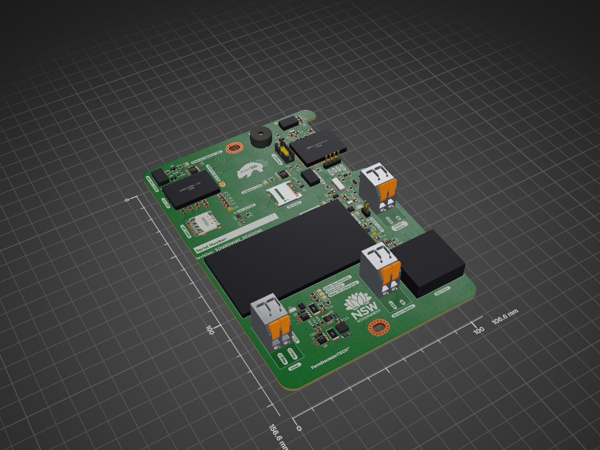
Enviro node is an open-source printed circuit board by DPIclimate, from the DPIclimate/enviro-node repository on GitHub, published under the MIT licence. It is a 2-layer board of 106.7 × 156.6 mm with 190 parts on 184 nets, routed with 836 tracks and 708 vias.
It is built around the PESD0402-140, BC847 and SS34LW RVG, with the 0685P2000-01, BSS214NW-TP and CONUFL001-SMD-T among its other parts. Its parts include 43 resistors, 32 capacitors, 10 diodes, 6 ICs and 6 connectors. It belongs with the ESP32 boards of this library.


About • Documentation • Hardware • License

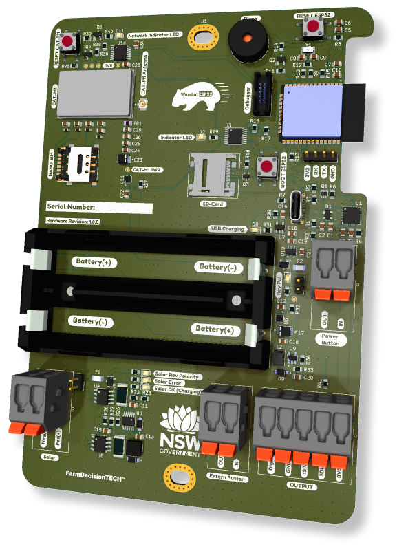
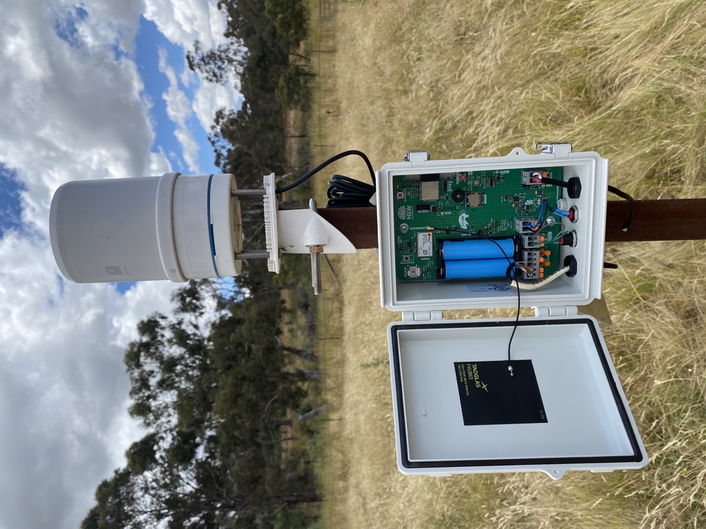
Enviro-node is a environmental monitoring node. Users can connect a number of sensors to a node. Data captured from these sensors is then sent to a database over MQTT.
The hardware was developed using KiCad. Source files can be found here. While sleeping the Enviro-node will consume ~70 µA.
=> Schematic
The device incorporates a ESP32 microcontroller to handle bluetooth functions and peripherals. The ESP32 has a very low sleep current of ~16 µA making it perfect for low-powered applications.
=> Schematic
Enviro-node features full debug capability when connected to an ESP-Prog (ESP32 debugger/programmer). It is recommended that you use a USB-to-TTL cable during development. This allows you to have the ESP-Prog connected to the Enviro-node while monitoring the ESP32's serial output via the USB-to-TTL connector.
The USB-C interface is only powered up when battery power is available. Do not attempt to power the board with the USB-C interface.
=> Schematic
The Enviro-node is powered by two 18650 LiPo cells connected in parallel (4.2 V). A current jumper is available to monitor current and voltage on an external device such as a multi-meter. The batteries feature reverse polarity detection and protection and an inline fuse.
An INA219 IC is connected to the battery to allow for real-time monitoring of battery current and voltage.
The batteries are recharged through a LT3652IMSE solar charging IC or via a USB-C battery charging IC (MCP73832). The default configuration allows for 12 V solar panels to be connected to the device; however, this can be set via a resistor divider.
The solar input features reverse polarity detection and protection as well as an inline fuse and charging/error indicators.
The charging current of the solar panel is limited to a maximum of 1 A and is monitored through another INA219 IC.
Most components on Enviro-node operate using 3.3 V for this a linear regulator is incorporated (XC6215B332MR-G). A power supply switch is connected to the output of this regulator to allow the ESP32 (and peripherals) to be manually turned off or restarted.
Although many SDI-12 devices will work with 3.3 V, the Enviro-node incorporates a 12 V step-up regulator (MIC2288YD5) to provide a stable 12 V (100 mA) supply. This IC can be toggled in the firmware via a GPIO pin and will be completely shutoff when not in use.
If a SDI-12 sensor requires a constant 12 V supply the current consumption of this step-up regulator is ~2 mA with no load.
=> Schematic
As a full debug interface is supplied and there are several operating interfaces (I2C, SPI, UART) the number of available GPIO pins on the ESP32 is limited. Therefore, an IO-expanded is provided (TCA9534) to control many IC's power consumption including CAT-M1, the SD-Card and 12 V power.
A LED is also connected the IO-expander that the user can configure.
For audible feedback a piezo buzzer is included and will play success and error tones while the device is being configured and on startup. Under normal conditions the piezo buzzer will be quiet.
An external programmable button is connected to a GPIO input pin on the ESP32. On startup if this button is held down the device will enter a programmable state whereby BluetoothLE will be enabled and a UART CLI interface will become available. Once the user types "exit\r" the CLI will be exited and normal operations will continue.
Environmental monitoring requires a SD-Card to ensure data is captured even when communications are down. The Enviro-node provides a top entry, Micro-SD card slot that can be disconnected from its power supply via a GPIO pin (see IO-Expander above).
A full SDI-12 interface is provided. No level-shifting is incorporated as the ESP32 can handle 5 V. Users can either use the 12 V output and toggle the output on-and-off or use the 3.3 V output for always on devices.
A digital pin is provided to the user to count pulses originating from a Tipping Bucket or wind-speed sensor.
=> Schematic
The Enviro-node uses CAT-M1 to send messages (containing JSON encoded data) over MQTT. For this a SARA-R5 modem is incorporated into the design. This modem communicates with the ESP32 microcontroller over AT-commands via a Serial (UART) interface.
Note A compatible nano-sim card is required for this functionality of the device. For Australian users Telstra has a M2M service or there are other global services such as Hologram.
The modem is directly powered by the 18650 batteries (as the modem can draw ~500 mA) and can be turned off and on via a GPIO pin (see IO-Expander above). A network indicator LED will indicate network registration status.
The firmware source code is located in the firmware/wombat directory. It is structured as a platformio project.
The install_pio.sh script will install platformio and copy the Wombat board files into the installation.
After running the script and adding ~/.platformio/penv/bin to the PATH, the firmware can be compiled with the command pio run.
This project is MIT licensed, as found in the LICENCE file.
| Qty | Value | Footprint | References |
|---|---|---|---|
| 10 | 10K | Resistor_SMD:R_0805_2012Metric | R5, R6, R8, R11, R13, R15, R18, R23, R36, R39 |
| 8 | 0.1uF | Capacitor_SMD:C_0805_2012Metric | C3, C6, C7, C21, C24, C28, C33, C34 |
| 6 | 1K | Resistor_SMD:R_0805_2012Metric | R4, R14, R19, R31, R35, R40 |
| 5 | 1uF | Capacitor_SMD:C_0805_2012Metric | C5, C12, C13, C19, C22 |
| 4 | 47pF | Capacitor_SMD:C_0805_2012Metric | C27, C30, C31, C32 |
| 4 | PESD0402-140 | PESD0402-140:PESD0402-140 | CR1, CR2, CR3, CR4 |
| 3 | 0 | Resistor_SMD:R_0805_2012Metric | R9, R10, R41 |
| 3 | 10uF | Capacitor_SMD:C_0805_2012Metric | C11, C15, C20 |
| 3 | 2604-3102 | 2604-3102:2604-3102 | J4, J7, J10 |
| 3 | 2K | Resistor_SMD:R_0805_2012Metric | R20, R24, R25 |
| 3 | 4.7K | Resistor_SMD:R_0805_2012Metric | R16, R17, R34 |
| 3 | 4.7uF | Capacitor_SMD:C_0805_2012Metric | C4, C14, C16 |
| 3 | BC847 | Package_TO_SOT_SMD:SOT-23 | Q2, Q4, Q5 |
| 3 | LED(Red) | LED_SMD:LED_0805_2012Metric | D3, D5, D10 |
| 3 | LOGO | LOGO | G***, G***, G*** |
| 3 | SS34LW_RVG | SS34LW_RVG:SODFL3718X102N | D6, D7, D9 |
| 2 | 0.1 | Resistor_SMD:R_2512_6332Metric | R21, R30 |
| 2 | 0.1uF | Capacitor_Tantalum_SMD:CP_EIA-2012-12_Kemet-R | C17, C23 |
| 2 | 0685P2000-01 | 0685P2000-01:0685P2000-01 | F1, F2 |
| 2 | 100K | Resistor_SMD:R_0805_2012Metric | R32, R37 |
| 2 | 12pF | Capacitor_SMD:C_0805_2012Metric | C8, C9 |
| 2 | 47K | Resistor_SMD:R_0805_2012Metric | R33, R38 |
| 2 | 5.1K | Resistor_SMD:R_0805_2012Metric | R3, R7 |
| 2 | G*** | kibuzzard-6397AB25 | kibuzzard-6397AB25, kibuzzard-6397AB25 |
| 2 | G*** | kibuzzard-639A4BB4 | kibuzzard-639A4BB4, kibuzzard-639A4BB4 |
| 2 | G*** | kibuzzard-635F8A8D | kibuzzard-635F8A8D, kibuzzard-635F8A8D |
| 2 | G*** | kibuzzard-635F8A75 | kibuzzard-635F8A75, kibuzzard-635F8A75 |
| 2 | G*** | kibuzzard-6397AB35 | kibuzzard-6397AB35, kibuzzard-6397AB35 |
| 2 | G*** | kibuzzard-639A4BC1 | kibuzzard-639A4BC1, kibuzzard-639A4BC1 |
| 2 | INA219BxD | Package_SO:SOIC-8_3.9x4.9mm_P1.27mm | U4, U8 |
| 2 | LED(Green) | LED_SMD:LED_0805_2012Metric | D4, D8 |
| 2 | LED(Orange) | LED_SMD:LED_0805_2012Metric | D2, D11 |
| 2 | MountingHole | MountingHole:MountingHole_4.3x6.2mm_M4_Pad_Via | H1, H2 |
| 2 | SSM3J340R_LF | SSM3J340R_LF:SSM3J340R_LF | MOSFET1, MOSFET2 |
| 2 | TPS22967DSGR | TPS22967DSGR:SON50P200X200X80-9N | U6, U11 |
| 1 | 0 | Resistor_THT:R_Axial_DIN0207_L6.3mm_D2.5mm_P10.16mm_Horizontal | R42 |
| 1 | 1049P | 1049P:1049P | B1 |
| 1 | 10K | Resistor_THT:R_Axial_DIN0207_L6.3mm_D2.5mm_P10.16mm_Horizontal | R43 |
| 1 | 10M | Resistor_SMD:R_0805_2012Metric | R12 |
| 1 | 10nF | Capacitor_SMD:C_0805_2012Metric | C25 |
| 1 | 12V_EN | TestPoint:TestPoint_Pad_D1.0mm | TP1 |
| 1 | 15pF | Capacitor_SMD:C_0805_2012Metric | C29 |
| 1 | 180K | Resistor_SMD:R_0805_2012Metric | R26 |
| 1 | 1V8 | TestPoint:TestPoint_Pad_D1.0mm | TP6 |
| 1 | 2.2uF | Capacitor_SMD:C_0805_2012Metric | C18 |
| 1 | 21K | Resistor_SMD:R_0805_2012Metric | R22 |
| 1 | 22.1K | Resistor_SMD:R_0805_2012Metric | R1 |
| 1 | 22uF | Capacitor_SMD:C_0805_2012Metric | C10 |
| 1 | 2604-3105 | 2604-3105:2604-3105 | J6 |
| 1 | 3.2K | Resistor_SMD:R_0805_2012Metric | R29 |
| 1 | 32.768KHz | ABS07AIG-32:XTAL320X150X90 | Y1 |
| 1 | 330K | Resistor_SMD:R_0805_2012Metric | R28 |
| 1 | 47.5K | Resistor_SMD:R_0805_2012Metric | R2 |
| 1 | 68pF | Capacitor_SMD:C_0805_2012Metric | C26 |
| 1 | 91K | Resistor_SMD:R_0805_2012Metric | R27 |
| 1 | BAT_CRNT_JMPR | Connector_PinHeader_2.54mm:PinHeader_1x02_P2.54mm_Vertical | J9 |
| 1 | BOOT | 1977223-6:1977223-6 | SW1 |
| 1 | BSS214NW | Package_TO_SOT_SMD:SOT-323_SC-70 | Q3 |
| 1 | CAT_M1_RST | 1977223-6:1977223-6 | SW3 |
| 1 | CONUFL001-SMD-T | CONUFL001-SMD-T:LINX_CONUFL001-SMD-T | J11 |
| 1 | CP2102N-Axx-xQFN28 | Package_DFN_QFN:QFN-28-1EP_5x5mm_P0.5mm_EP3.35x3.35mm | U1 |
| 1 | ESD_RST_IN | Resistor_SMD:R_0805_2012Metric | RV1 |
| 1 | ESP32-WROOM-32E_(16MB) | ESP32-WROOM-32E__16MB_:XCVR_ESP32-WROOM-32E_(16MB) | U2 |
| 1 | FBMH2012HM221-TV | FBMH2012HM221-TV:BEADC2012X105N | FB1 |
| 1 | G*** | kibuzzard-63C78316 | kibuzzard-63C78316 |
| 1 | G*** | kibuzzard-63932346 | kibuzzard-63932346 |
| 1 | G*** | kibuzzard-6396A3EF | kibuzzard-6396A3EF |
| 1 | G*** | kibuzzard-6396A450 | kibuzzard-6396A450 |
| 1 | G*** | kibuzzard-639A4BEA | kibuzzard-639A4BEA |
| 1 | G*** | kibuzzard-63932369 | kibuzzard-63932369 |
| 1 | G*** | kibuzzard-636098FD | kibuzzard-636098FD |
| 1 | G*** | kibuzzard-6397BE2B | kibuzzard-6397BE2B |
| 1 | G*** | kibuzzard-63606B50 | kibuzzard-63606B50 |
| 1 | G*** | kibuzzard-635FB066 | kibuzzard-635FB066 |
| 1 | G*** | kibuzzard-6374791F | kibuzzard-6374791F |
| 1 | G*** | kibuzzard-63606B27 | kibuzzard-63606B27 |
| 1 | G*** | kibuzzard-6396A474 | kibuzzard-6396A474 |
| 1 | G*** | kibuzzard-6396A059 | kibuzzard-6396A059 |
| 1 | G*** | kibuzzard-635FB008 | kibuzzard-635FB008 |
| 1 | G*** | kibuzzard-6360B45A | kibuzzard-6360B45A |
The 150 most common of 190 parts.
It measures 106.7 × 156.6 mm and has 2 copper layers, 1.6 mm thick.
190 parts, built around the PESD0402-140, BC847, SS34LW RVG and 0685P2000-01. The full list of its parts is on this page, with links to each part's symbol and footprint where PCBKit's library has them.
From the DPIclimate/enviro-node repository on GitHub, at the commit this page was made from: the board is electronics/motherboard/enviro-node/enviro-node.kicad_pcb and its schematic electronics/breakout/breakout.kicad_sch. PCBKit opens the board in the browser, with nothing to install.
Its repository publishes it under the MIT licence: you may reuse it on that licence's terms (keep the author's notice, and for a copyleft licence share your changes alike).


swiszczoo/adat_usb_interface
16-in, 16-out 4x ADAT <=> USB interface supporting USB Audio Class 2.0


Millisman/Quectel-BG95-LPWA-Module
Quectel BG95 LPWA Module board with integrated GPS & GSM

DPIclimate/ag-node
Automatic multi-weigh-station for measuring the live-weight of sheep in remote locations.


radioelf/Arduino-Due-mod-for-GPIO-compatible-Raspberry-Pi
PCB arduino Due para DuePi y Gpio Raspberry Pi

