2 layers48.3 × 123.8 mm
Altimeter v2
pimbongaerts/altimeter
Underwater sonar/USBL interface for photogrammetry surveys. PCB design files and Arduino code.
74 parts4

 donoghdb/local-zappi12
A dedicated hardware implant for Myenergi Zappi V2.x EV Chargers. This project interfaces directly with the Zappi's internal control bus to provide Local MQTT, Home Assistant, and Web Control without relying on the…
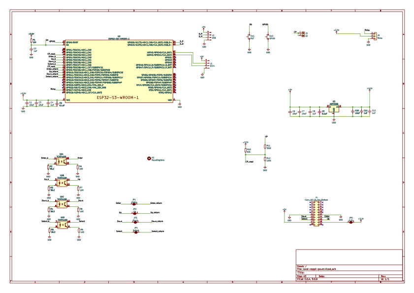
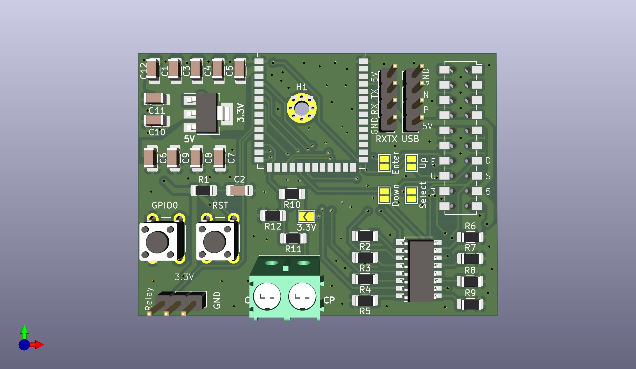
Local zappi power is an open-source printed circuit board by donoghdb, from the donoghdb/local-zappi repository on GitHub, published under the MIT licence. It is a 2-layer board of 60.3 × 44 mm with 40 parts on 65 nets, routed with 243 tracks and 112 vias.
It is built around the ESP32-S3-WROOM-1-N8 and TCMT4100. Its parts include 12 capacitors, 12 resistors, 5 connectors, 3 ICs and 2 switches. It belongs with the ESP32 boards of this library.


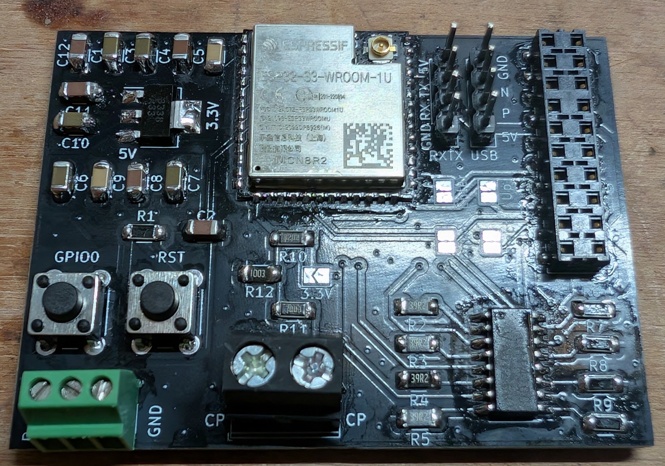
A dedicated hardware implant for Myenergi Zappi V2.x EV Chargers. This project interfaces directly with the Zappi's internal control bus to provide Local MQTT, Home Assistant, and Web Control without relying on the Myenergi Cloud or Hub. It is intended to action on the 4 external buttons while monitoring the EVSE CP line conversation between the Zappi and the car. It does not affect the software of the Zappi nor does it affect anything else. So it can be removed without affecting anything else.
This device is installed INSIDE a 240V/400V EV Charger.
This PCB intercepts the connection between the Zappi Main Control Board and the Front Panel (Display & Buttons).
The design utilizes an ESP32-S3-WROOM-1 and integrates via the internal 20-pin Ribbon Header.
| Signal | Function | Connection |
|---|---|---|
| 5V / GND | Power Supply | Taken from Zappi internal header. |
| Buttons | Enter, Up, Down, Select | Bi-directional: Reads physical presses & triggers simulated presses via Optocouplers (TCMT4100). |
| CP Signal | J1772 State Detection | Read ±12V Pilot Signal. |
| Boost Relay | e-Sense Port trigger | Enable via relay. |
Based on PCB Revision 1.1
This project supports two firmware paths depending on your needs:
Best for Home Assistant users. Provides native integration with zero coding.
esphome/zappi.yaml and esphome/zappi_logic.h to your ESPHome directory.Best for standalone use or custom MQTT setups.
To keep your WiFi and MQTT passwords safe, this project uses a separate credentials file that is ignored by Git.
src/credentials.cppCreate a new file in the src/ folder named credentials.cpp and copy the code below. Update the values with your actual network details.
#include "credentials.h"
#include <Arduino.h> // for IPAddress

// WiFi Credentials
const char* ssid = "YOUR_WIFI_SSID";
const char* password = "YOUR_WIFI_PASSWORD";

// MQTT Broker Details
const char* mqttServer = "192.168.1.50";
const int mqttPort = 1883;
const char* mqttUser = "homeassistant";
const char* mqttPassword = "mqtt_password";
const char* mqttClientId = "Zappi_Controller";

// Static IP Configuration (Optional)
// Set to 0.0.0.0 if you want to use DHCP
IPAddress staticIP(192, 168, 1, 200);
IPAddress gateway(192, 168, 1, 1);
IPAddress subnet(255, 255, 255, 0);The device uses the base topic zappi/ (configurable).
zappi/button/...zappi/sensor/...zappi/status (online/offline)zappi/switch/zap_sch_en/command (ON/OFF)zappi/text/zap_sch_start/set (HH:MM)zappi/text/zap_sch_end/set (HH:MM)zappi/time/set_epoch (Epoch Timestamp)This method allows you to use the full Web Interface and custom C++ logic.
firmware_custom folder in VS Code with the PlatformIO extension installed.platformio.ini and ensure the OTA lines are commented out (so it uses USB upload by default):
; upload_protocol = espota
; upload_port = 192.168.1.XThe HTML files live in a separate partition called LittleFS. You must upload this once, or the web page will be blank.
Zappi-AP (Password: password123 or as configured).http://192.168.4.1 (or the IP assigned by your router).Once the device is installed inside the Zappi case, you can update it wirelessly:
192.168.1.50).platformio.ini and uncomment the OTA lines:
upload_protocol = espota
upload_port = 192.168.1.50  ; Replace with your actual IP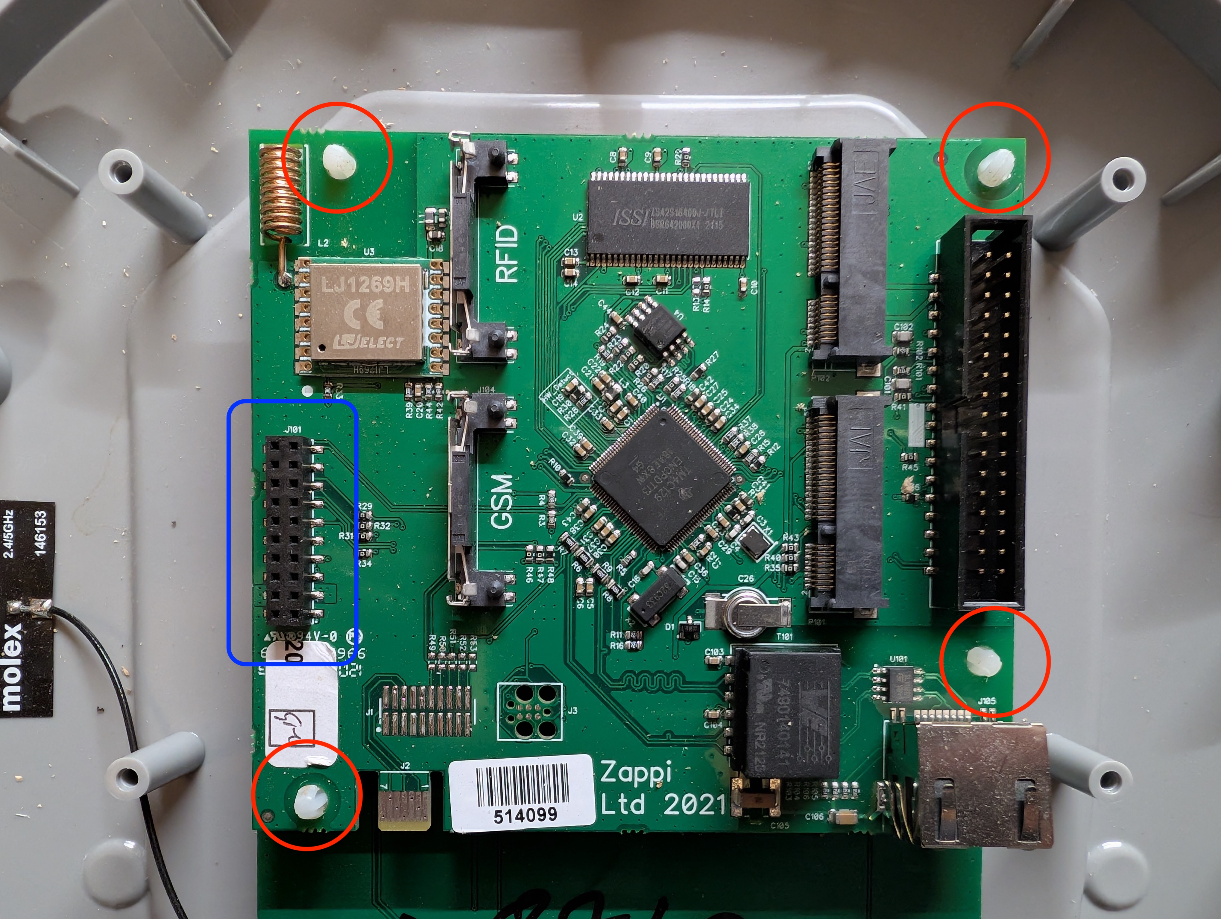
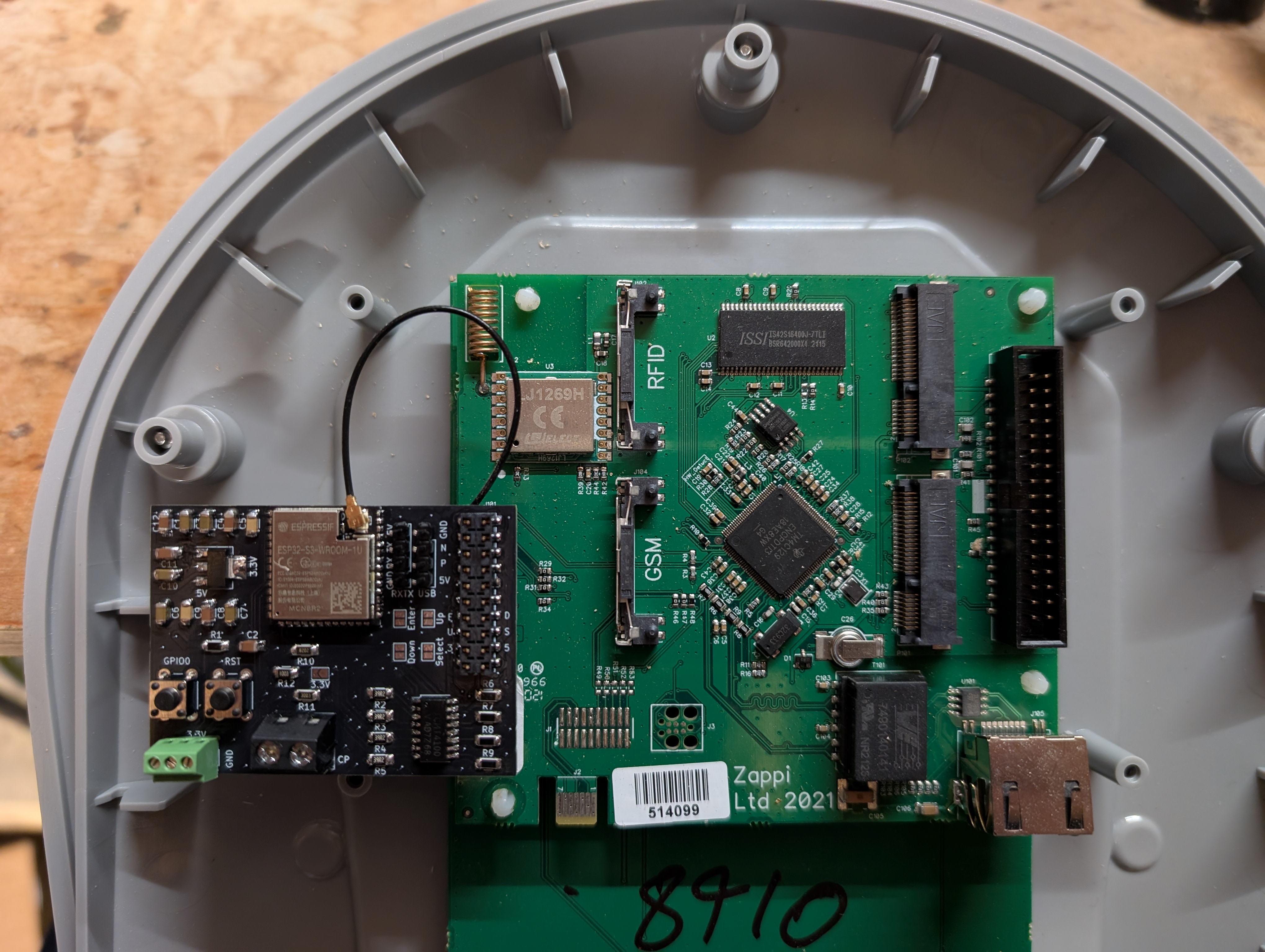
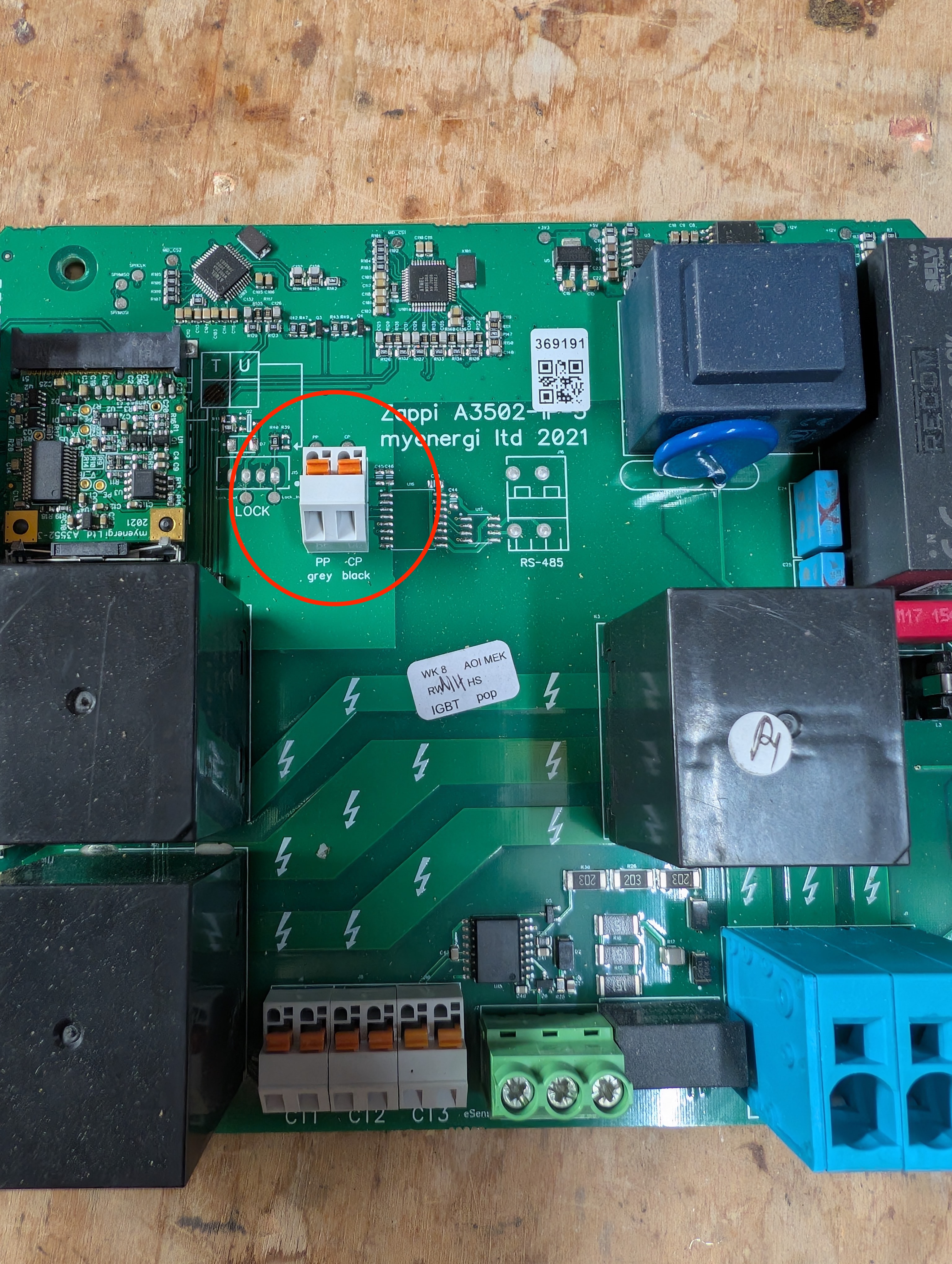
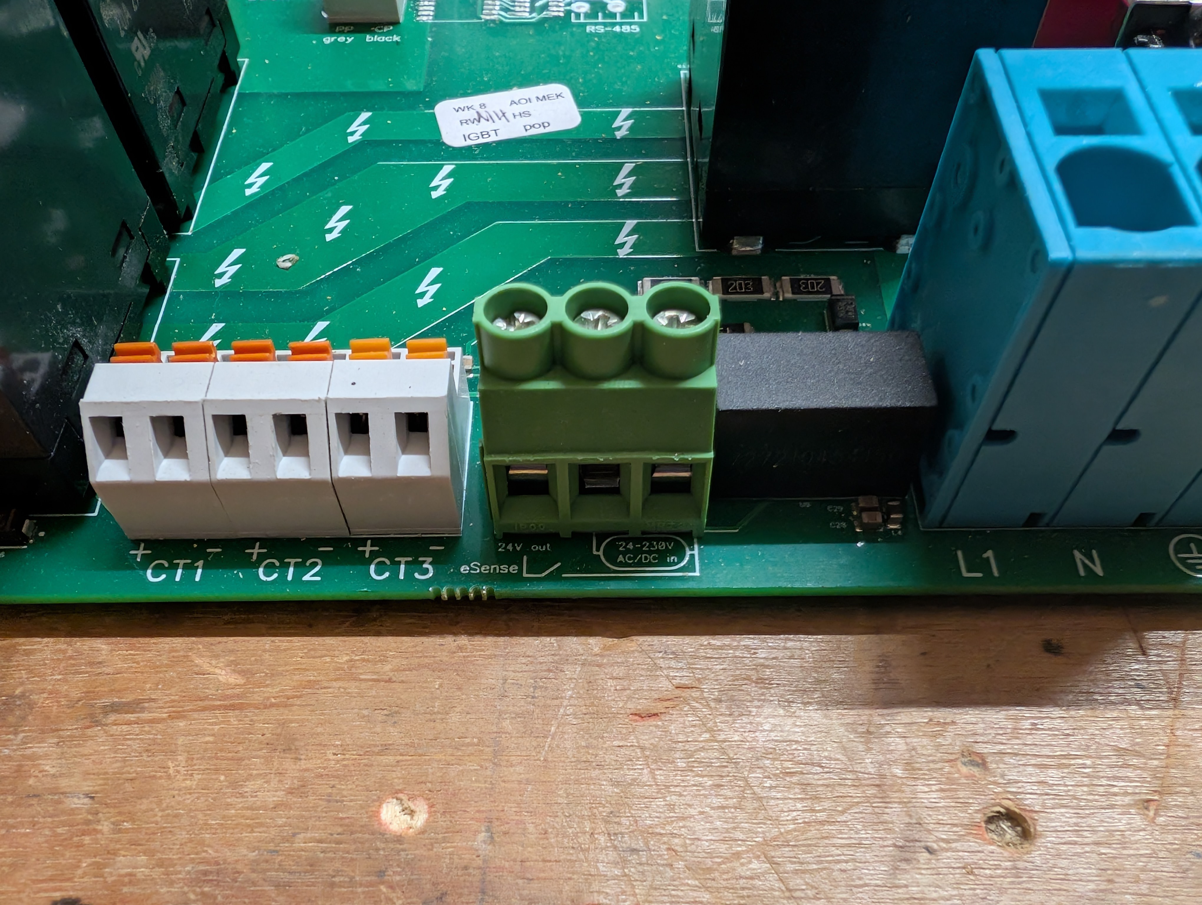
This project requires a custom PCB or a perfboard setup designed to fit inside the Zappi case. There is more Decoupling capacitators than required. Sometimes the power rails dip when the Zappi triggers its own relays.
| Ref | Component | Description | Notes |
|---|---|---|---|
| U2 | ESP32-S3-WROOM-1 | MCU Module | Schematic specifies WROOM-1 (PCB Antenna). If using the 1U version, connect an external IPEX antenna. |
| U3 | ADP3338 | 3.3V LDO Regulator | Steps down the Zappi 5V rail to 3.3V for the ESP32. |
| U1 | TCMT4100 | Quad Optocoupler | U1: Simulates button presses. |
| Ref | Value | Quantity | Description |
|---|---|---|---|
| R1 | 10kΩ | 1 | Pull up to 3.3V for ESP32 Enable Pin. |
| R2-R5 | 39.2Ω | 4 | Current limiting for Optocoupler LEDs. |
| R6-R9 | 100Ω | 4 | Pull/Protection for button return lines. |
| R10 | 82kΩ | 1 | Pull up to 3.3V Pilot Signal divider (CP to ADC), 1% Tolerance required. |
| R11 | 300kΩ | 1 | High-side Pilot Signal divider (CP to ADC), 1% Tolerance required. |
| R12 | 100kΩ | 1 | Low-side Pilot Signal divider (ADC to GND), 1% Tolerance required. |
| C6, C7, C10, C1, C3 | 10µF | 4 | Bulk capacitance for LDO & 3.3V Rails. |
| C2, C4, C8, C11, C12 | 1µF | 4 | Stability capacitance for LDO. |
| C5, C9 | 0.1µF | 2 | Decoupling for ESP32 and Power rails. |
| Component | Quantity | Purpose |
|---|---|---|
| 20-Pin Header | 1 | 2x10 Samtec (HLE-110-02-L-DV-BE-K-TR) to interface with Zappi mainboard. |
| 2-Pin Terminal | 1 | Screw terminal for CP (Pilot) wire connection. |
| 3-Pin Header/Terminal | 1 | Optional Relay/GPIO breakout (JP5). |
| Buttons | 2 | Reset and GPIO 0 button. |
| Mini Relay | 1 | Optional: Adafruit STEMMA Non-Latching Mini Relay. |
The device includes a System Time Sensor (sensor.system_time) to show you exactly what time the internal clock thinks it is.
zappi/time/set_epoch.The Control Pilot (CP) line communicates the state of the EVSE to the car using specific voltage levels (+12V, +9V, +6V) and a 1kHz PWM signal.
Since we are using a Passive Resistor Divider (300kΩ / 100kΩ), it is critical to verify the voltage levels before relying on the automation.
Before installing the unit into the Zappi, you can verify the voltage divider logic using a DC Power Supply or a simple 9V battery.
Once installed in the Zappi, use the WebSerial (Custom Firmware) or Home Assistant Logs (ESPHome) to view the raw ADC readings.
The code looks for the Peak Voltage of the signal. Here is what you should see in the logs:
| State | J1772 Voltage | Divider Output | Target ADC Raw |
|---|---|---|---|
| A (Unplugged) | +12V | ~3.0V | 3600 - 4095 |
| B (Connected) | +9V | ~2.25V | 3100 - 3600 |
| C (Charging) | +6V (PWM) | ~1.5V | 2500 - 3100 |
| D (Ventilation) | +3V (PWM) | ~0.75V | 1900 - 2500 |
| F (Error/Fault) | -12V | -3.0V* | < 1500 |
> Note: The passive divider will pass negative voltages to the GPIO. Ensure your protection diode is in place, or that the ESP32 inputs are clamped effectively to prevent damage during State F.
When the car enters State C (Charging), the Zappi generates a 1kHz Square Wave.
Amps = Duty Cycle x 0.6| Qty | Value | Footprint | References |
|---|---|---|---|
| 5 | 10uF | Capacitor_SMD:C_1206_3216Metric_Pad1.33x1.80mm_HandSolder | C1, C3, C6, C7, C10 |
| 5 | 1uF | Capacitor_SMD:C_1206_3216Metric_Pad1.33x1.80mm_HandSolder | C2, C4, C8, C11, C12 |
| 4 | 100 | Resistor_SMD:R_1206_3216Metric_Pad1.30x1.75mm_HandSolder | R6, R7, R8, R9 |
| 4 | 39.2 | Resistor_SMD:R_1206_3216Metric_Pad1.30x1.75mm_HandSolder | R2, R3, R4, R5 |
| 2 | 0.1uF | Capacitor_SMD:C_1206_3216Metric_Pad1.33x1.80mm_HandSolder | C5, C9 |
| 1 | 100k | Resistor_SMD:R_1206_3216Metric_Pad1.30x1.75mm_HandSolder | R12 |
| 1 | 10k | Resistor_SMD:R_1206_3216Metric_Pad1.30x1.75mm_HandSolder | R1 |
| 1 | 3.3V | Jumper:SolderJumper-2_P1.3mm_Open_TrianglePad1.0x1.5mm | JP5 |
| 1 | 300k | Resistor_SMD:R_1206_3216Metric_Pad1.30x1.75mm_HandSolder | R11 |
| 1 | 82k | Resistor_SMD:R_1206_3216Metric_Pad1.30x1.75mm_HandSolder | R10 |
| 1 | A0 | TerminalBlock_Phoenix:TerminalBlock_Phoenix_PT-1,5-2-5.0-H_1x02_P5.00mm_Horizontal | J3 |
| 1 | ADP3338 | Package_TO_SOT_SMD:SOT-223-3_TabPin2 | U3 |
| 1 | Conn_02x10_Top_Bottom | Connector_Samtec_HLE_SMD:Samtec_HLE-110-02-xxx-DV-BE_2x10_P2.54mm_Horizontal | J4 |
| 1 | Down | Jumper:SolderJumper-2_P1.3mm_Bridged2Bar_Pad1.0x1.5mm | JP3 |
| 1 | ESP32-S3-WROOM-1 | Espressif:ESP32-S3-WROOM-1 | U2 |
| 1 | Enter | Jumper:SolderJumper-2_P1.3mm_Bridged2Bar_Pad1.0x1.5mm | JP1 |
| 1 | GND | Connector_PinHeader_2.54mm:PinHeader_1x03_P2.54mm_Vertical | J5 |
| 1 | GPIO0 | Button_Switch_THT:SW_PUSH_6mm_H4.3mm | SW2 |
| 1 | MountingHole | MountingHole:MountingHole_2.5mm_Pad_Via | H1 |
| 1 | RST | Button_Switch_THT:SW_PUSH_6mm_H4.3mm | SW1 |
| 1 | RXTX | Connector_PinHeader_2.54mm:PinHeader_1x04_P2.54mm_Vertical | J1 |
| 1 | Select | Jumper:SolderJumper-2_P1.3mm_Bridged2Bar_Pad1.0x1.5mm | JP4 |
| 1 | TCMT4100 | Package_SO:SOP-16_4.4x10.4mm_P1.27mm | U1 |
| 1 | USB | Connector_PinHeader_2.54mm:PinHeader_1x04_P2.54mm_Vertical | J2 |
| 1 | Up | Jumper:SolderJumper-2_P1.3mm_Bridged2Bar_Pad1.0x1.5mm | JP2 |
pimbongaerts/altimeter
Underwater sonar/USBL interface for photogrammetry surveys. PCB design files and Arduino code.


risingtideresearch/CAN-Power-Control
CAN device for switching high-current DC loads and reading sensors and switch closures

wojtek-00/HomeAutomation
A modular home automation system built around ESPHome, custom PCB design (KiCad), and 3D-printed enclosures.

joeycastillo/The-Open-Book
For details on how to build, test and use Open Book, I've made documentation available here.

hackclub/OnBoard
💡 Join 1,000 teenagers and make your first PCB with a $100 grant!

bitaxeorg/bitaxeGamma
Bitaxe based on the BM1370 from the S21 Pro
It measures 60.3 × 44 mm and has 2 copper layers, 1.6 mm thick.
40 parts, built around the ESP32-S3-WROOM-1-N8 and TCMT4100. The full list of its parts is on this page, with links to each part's symbol and footprint where PCBKit's library has them.
From the donoghdb/local-zappi repository on GitHub, at the commit this page was made from: the board is kicad/local-zappi-power/local-zappi-power.kicad_pcb and its schematic kicad/local-zappi-power/local-zappi-power.kicad_sch. PCBKit opens the board in the browser, with nothing to install.
Its repository publishes it under the MIT licence: you may reuse it on that licence's terms (keep the author's notice, and for a copyleft licence share your changes alike).