Skip to the content
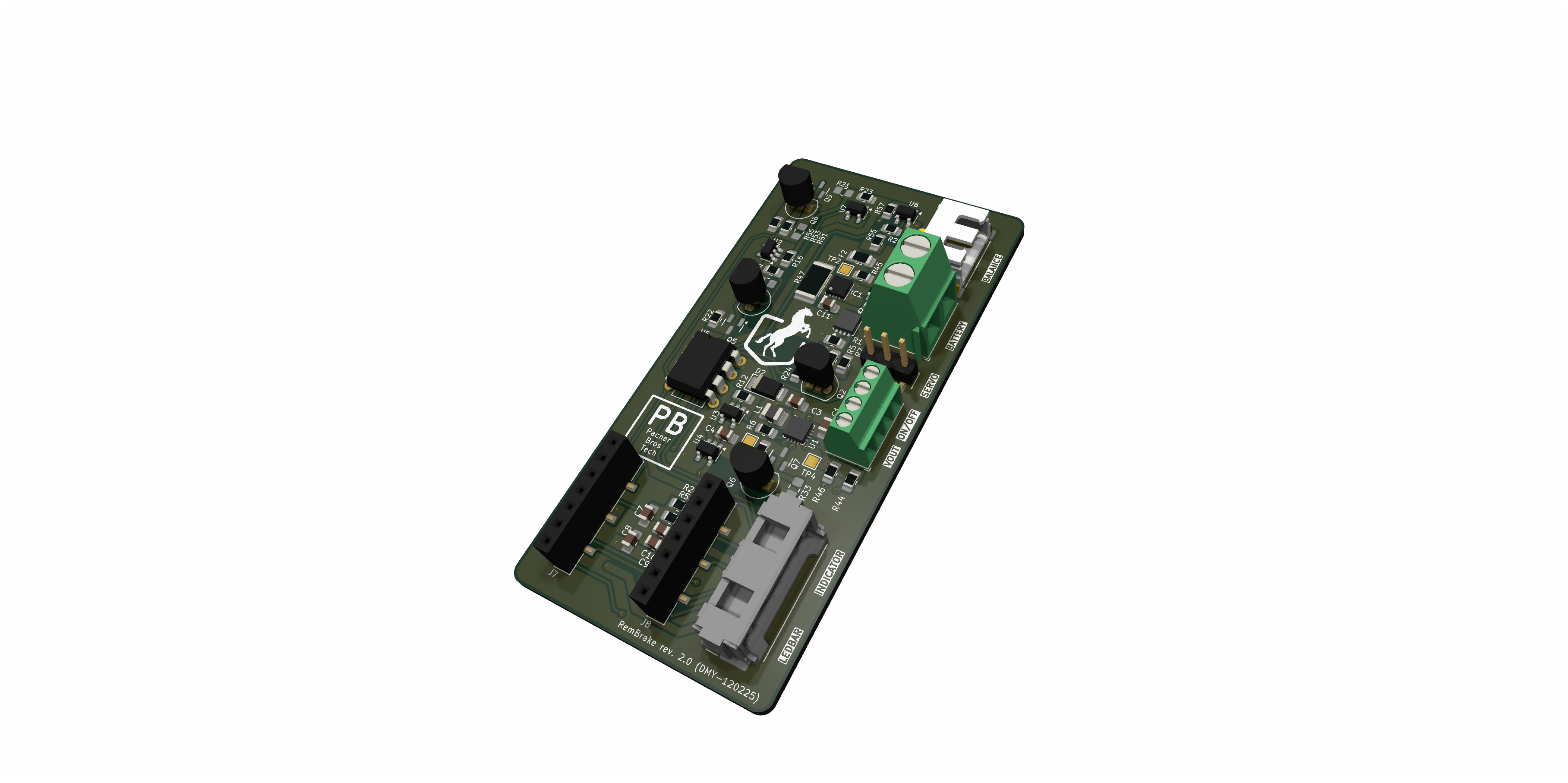
11 layers42 × 24 mmLEDbar, the printed circuit board in 3D

electronic system to control breaks on handbikes remotely

Size
42 × 24 mm
Copper layers
11
Thickness
1.6 mm
Parts
26
Nets
105
Pads
107
Tracks, vias
0, 0
Pours
1
Routed
Not yet
KiCad
KiCad 8.99 (file 20241010)
Created
12 Sep 2024
Updated
10 Sep 2025

Overview

LEDbar is an open-source printed circuit board by dodotronix, from the dodotronix/RemBrake repository on GitHub. It is an 11-layer board of 42 × 24 mm with 26 parts on 105 nets.

It is built around the STP16CP05XT. Its parts include 10 capacitors, 10 resistors, 3 connectors and 2 ICs. It belongs with the radio and wireless and robots and motor control boards of this library.
Main components

1

README

README.md

RemBrake - remote brake system for handbikes

PCB picture

Introduction

  • TODO explain what the RemBrake, why we decided to create this project

Assembling RemBrake

  • TODO explain how to use the kicad data
  • TODO how to solder the modules on the RemBrake PCB
  • TODO how to connect the wires

Prepare the module

  1. load the circuitpython to the QT Py RP2040
  2. press and hold BOOT button and then press RST button
  3. you should see now RPI partition mounted to your PC
  4. download CircuitPython bootloader (.uf2 file) from circuitpython.org
  5. drag and drop the file onto the partition
  6. it takes few moments and you should see your partition name turn to CIRCUITPYTHON

Upload RemBrake files + necessary modules

  1. go to the folder fw folder
  2. run $ make prepare
  3. move the folder target to your CIRCPITPYTHON partition

Features

  • TODO how the PCB behaves (charging, running, error)
  • TODO what the different colors mean

Possible further development

  • Bidirectional remote contoller that the assistant can see the battery status
  • Accelerometer feedback, to adjust braking power according to the situation
  • Using hydraulic piston actuator to move with the brake directly, which could shrink significantly the size of the package
  • designing custom usb-c charger to avoid the hustle with unprecise power management of the chinese module

Development

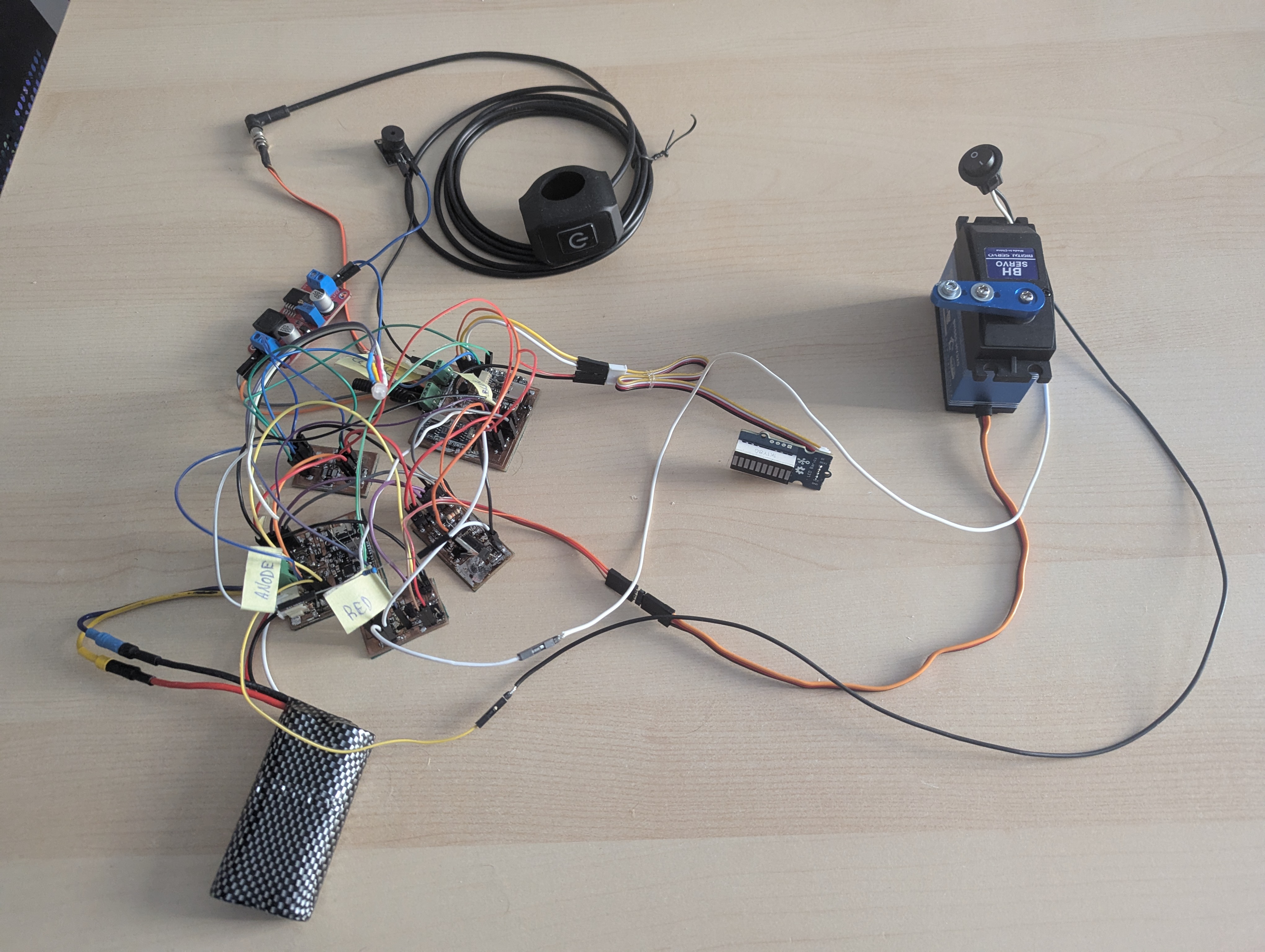
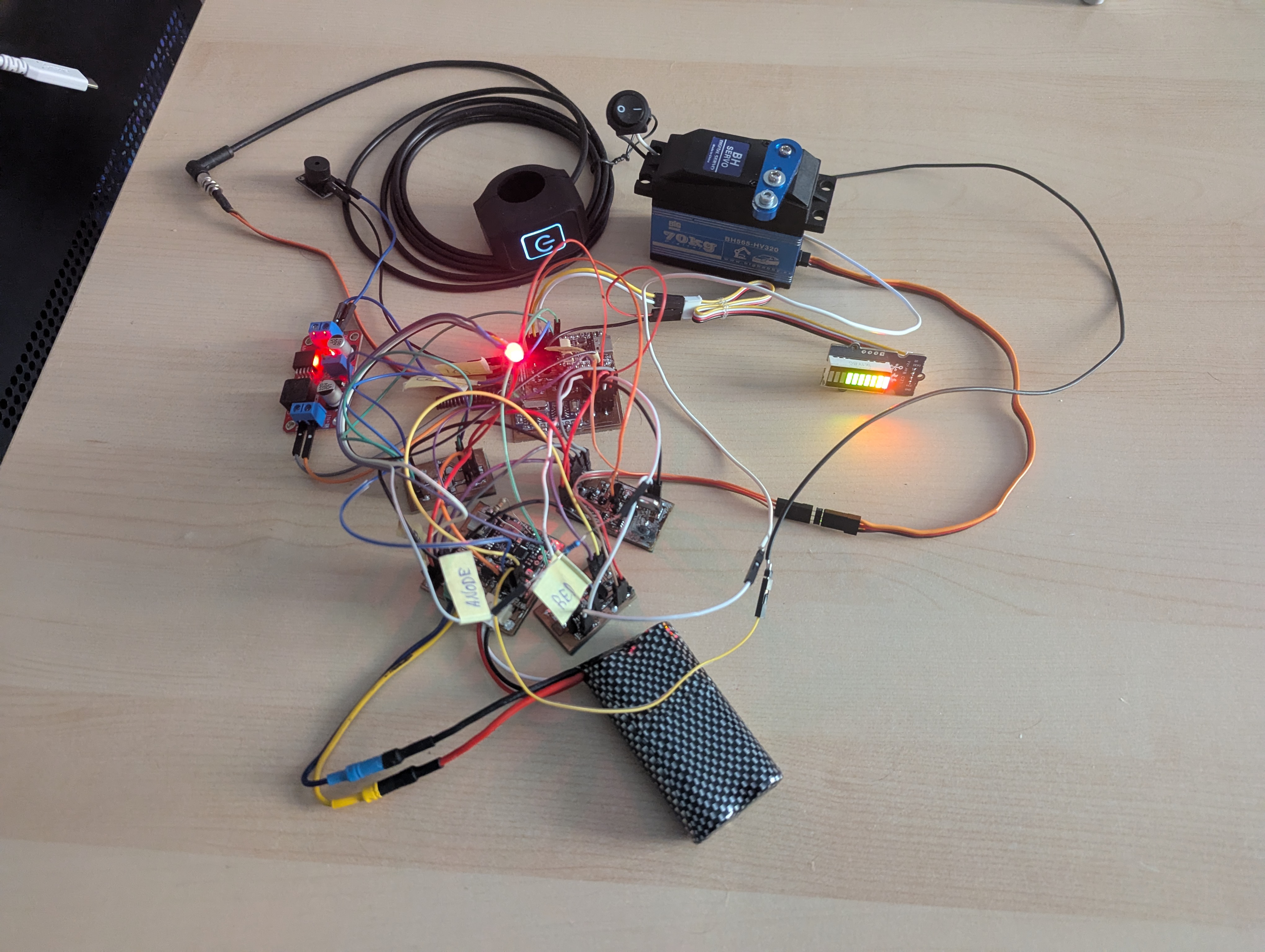
PCB inactive breakout modules PCB active breakout modules

Parts

26
QtyValueFootprintReferences
10CCapacitor_SMD:C_0402_1005MetricC1, C2, C3, C4, C5, C6, C7, C8, C9, C10
10RResistor_SMD:R_0402_1005MetricR1, R2, R3, R4, R5, R6, R7, R8, R9, R10
3Conn_01x04Connector_PinHeader_2.54mm:PinHeader_1x04_P2.54mm_VerticalJ1, J2, J3
1HDSP-4832_2Display:HLCP-J100BAR1
1LM358_DFNPackage_DFN_QFN:DFN-8-1EP_2x2mm_P0.5mm_EP1.05x1.75mmU2
1STP16CP05XTPackage_SO:TSSOP-24_4.4x7.8mm_P0.65mmU1

More from dodotronix/RemBrake

6
  • 2 layers40 × 80 mmRemBrake, the printed circuit board in 3D

    RemBrake

    dodotronix/RemBrake

    electronic system to control breaks on handbikes remotely

    127 parts
  • 2 layers143.8 × 99.6 mmBreakoutpcbs, the printed circuit board in 3D

    Breakoutpcbs

    dodotronix/RemBrake

    electronic system to control breaks on handbikes remotely

    108 parts
  • 11 layers31 × 18 mmUSBcharger, the printed circuit board in 3D

    USBcharger

    dodotronix/RemBrake

    electronic system to control breaks on handbikes remotely

    36 parts
  • 11 layers28.3 × 12.3 mmRFController, the printed circuit board in 3D

    RFController

    dodotronix/RemBrake

    electronic system to control breaks on handbikes remotely

    19 parts
  • 11 layers50 × 28 mmBoostConverter, the printed circuit board in 3D

    BoostConverter

    dodotronix/RemBrake

    electronic system to control breaks on handbikes remotely

    18 parts
  • 11 layers21 × 16 mmAccelSensor, the printed circuit board in 3D

    AccelSensor

    dodotronix/RemBrake

    electronic system to control breaks on handbikes remotely

    15 parts

Similar boards

  • 2 layers153 × 95.8 mmSpekky Matrix, the printed circuit board in 3D

    Spekky Matrix

    jc-SpaceXp/Spekky-Matrix

    Spectrum analyser displayed on a LED matrix board connected to a STM32 device

    390 parts1MIT
  • 4 layers177 × 91.8 mmOrrery circuit, the printed circuit board in 3D

    Orrery circuit

    Drummersbrother/vanity-electronics

    My various small-to-medium electronics (read: EDA) projects. Free for personal use only unless otherwise specified

    170 parts
  • 2 layers80 × 40 mmOSLB56317-XX Driver, the printed circuit board in 3D

    OSLB56317-XX Driver

    Electro707/OSLB56317_Driver

    A driver board and firmware for the OSLB56317 LED matrix

    35 partsGPL-3.0
  • 11 layers106.1 × 55.1 mmIDEFlex, the printed circuit board in 3D

    IDEFlex

    Redherring32/Xbox-Portable

    Fully portable original (2001) Xbox handheld using real hardware

    20 parts93
  • 11 layers44.6 × 31.6 mmNotecarrier Micro, the printed circuit board in 3D

    Notecarrier Micro

    Safecast/bGeigieZen

    bGiegieZen an Open Source Geiger Counter.

    33 parts24
  • 11 layers58 × 31.9 mmReader, the printed circuit board in 3D

    Reader

    bullestock/acsv2

    Rewrite of Access Control System in Django

    34 parts2GPL-3.0
  • 11 layers44 × 73 mmGb video pico breakout, the printed circuit board in 3D

    Gb video pico breakout

    chromalock/CGBLinkVideo

    Playing media on a gameboy color over the link cable, with the help of an RPi Pico

    15 parts39
  • 11 layers64 × 41.4 mmESPCB, the printed circuit board in 3D

    ESPCB

    shvmm/espcb-bms-comms

    An ESP32 series based PCB for implementing BMS comms to Solar Inverters

    13 partsLGPL-2.1

Questions

How big is the LEDbar PCB?

It measures 42 × 24 mm and has 11 copper layers, 1.6 mm thick.

What parts does the LEDbar use?

26 parts, built around the STP16CP05XT. The full list of its parts is on this page, with links to each part's symbol and footprint where PCBKit's library has them.

Where can I download the LEDbar KiCad files?

From the dodotronix/RemBrake repository on GitHub, at the commit this page was made from: the board is hw/LEDbar/LEDbar.kicad_pcb and its schematic hw/AccelSensor/AccelSensor.kicad_sch. PCBKit opens the board in the browser, with nothing to install.

Can I use the LEDbar design in my own project?

Its repository states no licence, so its author keeps all rights: ask dodotronix before reusing the design.