
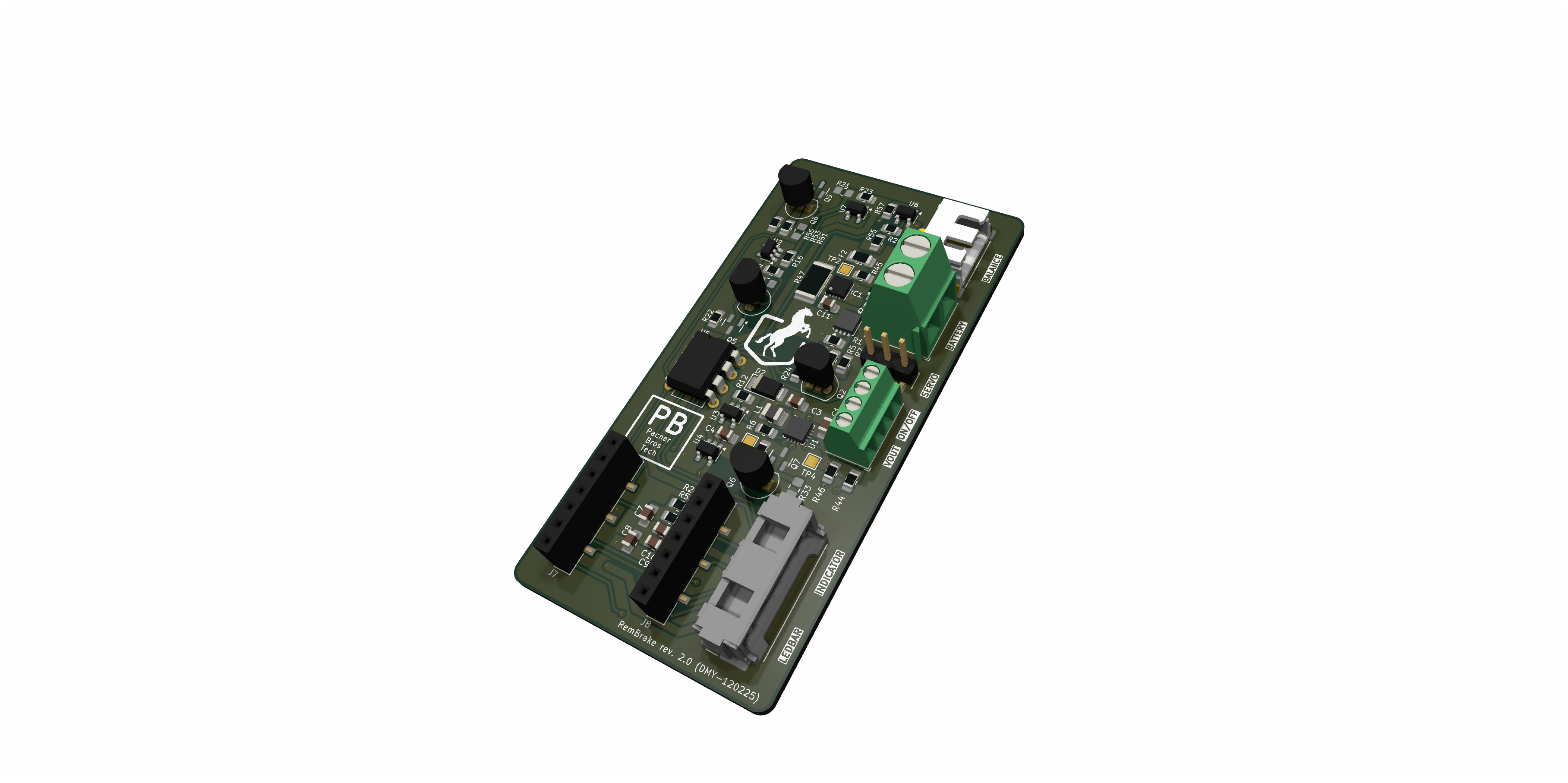
2 layers40 × 80 mm

 dodotronix/RemBrake
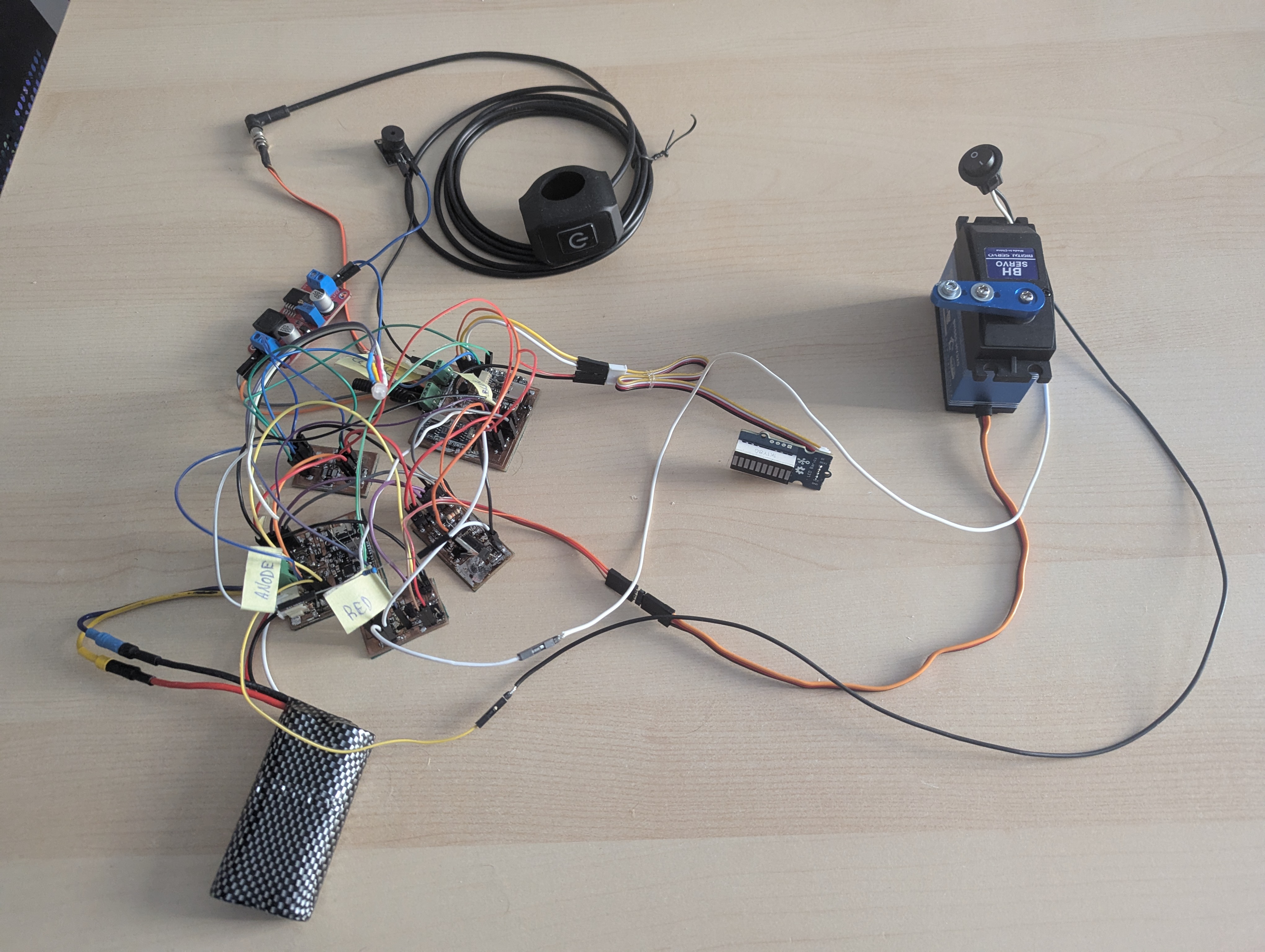
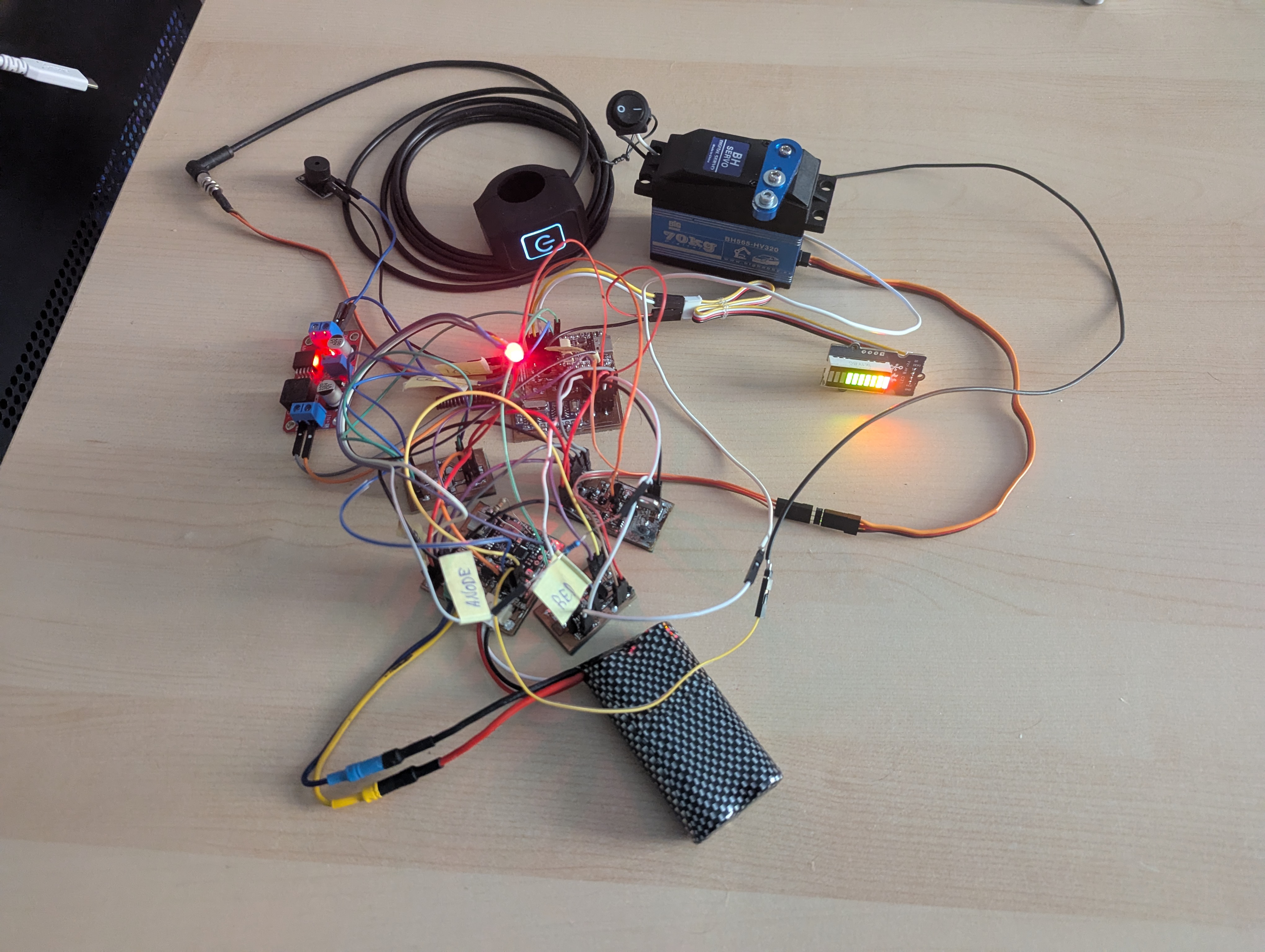
electronic system to control breaks on handbikes remotely
BoostConverter is an open-source printed circuit board by dodotronix, from the dodotronix/RemBrake repository on GitHub. It is an 11-layer board of 50 × 28 mm with 18 parts on 36 nets.
It is built around the LM2595S-5.0. Its parts include 4 capacitors, 3 diodes, 2 resistors, 2 connectors and 1 IC. It belongs with the radio and wireless and power boards of this library.
| Qty | Value | Footprint | References |
|---|---|---|---|
| 4 | MountingHole_Pad | TestPoint:TestPoint_Plated_Hole_D3.0mm | H1, H2, H3, H4 |
| 2 | C | Capacitor_SMD:C_0805_2012Metric | C3, C4 |
| 2 | C_Polarized | Capacitor_SMD:CP_Elec_8x10 | C1, C2 |
| 2 | DIODE | Diode_SMD:D_SMA | D1, D2 |
| 2 | R | Resistor_SMD:R_0805_2012Metric | R1, R2 |
| 2 | Screw_Terminal_01x02 | TerminalBlock_Phoenix:TerminalBlock_Phoenix_PT-1,5-2-3.5-H_1x02_P3.50mm_Horizontal | J1, J2 |
| 1 | L | Inductor_SMD:L_Bourns_SRR1260 | L1 |
| 1 | LED | LED_SMD:LED_0805_2012Metric | D3 |
| 1 | LM2595S-5 | Package_TO_SOT_SMD:TO-263-5_TabPin3 | U1 |
| 1 | R_Potentiometer | Potentiometer_THT:Potentiometer_Bourns_3266Y_Vertical | RV1 |


VishalSingh-ML/-12V-to-5V-Buck-Converter-LM2595-Based-PCB-Design-in-KiCad-
Complete 12V to 5V Buck Converter design using KiCad. Includes schematic, PCB layout, DRC clean-up, and Gerber file generation.

hspil/greenhouse-controller-pcb
Central controller for greenhouse automation project


Redherring32/Xbox-Portable
Fully portable original (2001) Xbox handheld using real hardware

chromalock/CGBLinkVideo
Playing media on a gameboy color over the link cable, with the help of an RPi Pico

shvmm/espcb-bms-comms
An ESP32 series based PCB for implementing BMS comms to Solar Inverters

ForestKatsch/unofficial-tesla-seat-controller
STM32G0-based controller for four seat motors, two ventilation fans, and the seat switchpack. Input is a regulated 12 V Mean Well power supply; record the exact model before system testing.
It measures 50 × 28 mm and has 11 copper layers, 1.6 mm thick.
18 parts, built around the LM2595S-5.0. The full list of its parts is on this page, with links to each part's symbol and footprint where PCBKit's library has them.
From the dodotronix/RemBrake repository on GitHub, at the commit this page was made from: the board is hw/BoostConverter/BoostConverter.kicad_pcb and its schematic hw/AccelSensor/AccelSensor.kicad_sch. PCBKit opens the board in the browser, with nothing to install.
Its repository states no licence, so its author keeps all rights: ask dodotronix before reusing the design.