2 layers147.3 × 95.3 mm
Nixie proj conflict-20171112-163801
dm2lct/tlnixie
PCB files for the Turmlabor nixie clock 2.0
117 parts11GPL-3.0

 dm2lct/Nixieclock_kit9
This is a Nixie-clock controlled by a ESP8266 module with NTP and MQTT support.
Nixie proj is an open-source printed circuit board by dm2lct, from the dm2lct/Nixieclock_kit repository on GitHub, published under the GPL-3.0 licence. It is a 2-layer board of 140 × 72.5 mm with 119 parts on 117 nets, routed with 1,262 tracks and 309 vias.
It is built around the ESP-12E, FT232RL and LM3478MA, with the MPSA92, WS2812B and BSS138 among its other parts. Its parts include 28 resistors, 20 capacitors, 12 transistors, 6 diodes and 4 switches. It belongs with the lEDs and displays and home automation and IoT boards and the ESP8266 boards of this library.


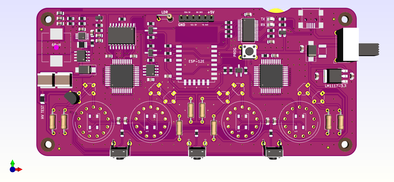
Feel free to build your own nixie clock from it.
The firmware can be found at https://codeberg.org/paul/nixie_clock
The documentation and assembly instructions are on https://wiki.turmlabor.de/index.php?title=Nixie_Uhr_Bausatz_2.1 (currently only in german, sorry!)
Features:
| Qty | Value | Footprint | References |
|---|---|---|---|
| 18 | 10k | Resistor_SMD:R_0805_2012Metric_Pad1.15x1.40mm_HandSolder | R2, R3, R206, R310, R401, R402, R403, R410, R411, R412, R413, R414, R416, R417, R418, R419 +2 |
| 14 | 2.2u | Capacitor_SMD:C_0805_2012Metric_Pad1.15x1.40mm_HandSolder | C1, C5, C6, C8, C14, C16, C17, C18, C19, C20, C21, C22, C23, C201 |
| 8 | MPSA92 | TO_SOT_Packages_THT:TO-92_Molded_Wide_Oval | Q202, Q203, Q204, Q205, Q206, Q207, Q208, Q209 |
| 4 | 10R | Resistor_SMD:R_0805_2012Metric_Pad1.15x1.40mm_HandSolder | R404, R405, R406, R407 |
| 4 | 330 | Resistors_THT:R_Axial_DIN0207_L6.3mm_D2.5mm_P10.16mm_Horizontal | 330, 330, 330, 330 |
| 4 | 330k | Resistors_THT:R_Axial_DIN0207_L6.3mm_D2.5mm_P10.16mm_Horizontal | 330k, 330k, 330k, 330k |
| 4 | Fiducial | Fiducial:Fiducial_0.75mm_Mask1.5mm | FID1, FID2, FID3, FID4 |
| 4 | IN14 | Version_2:IN-14-mod | TBE201, TBE202, TBE203, TBE204 |
| 4 | WS2812B | LED_SMD:LED_WS2812B_PLCC4_5.0x5.0mm_P3.2mm | LED401, LED402, LED403, LED404 |
| 3 | 22u | Capacitor_SMD:C_0805_2012Metric_Pad1.15x1.40mm_HandSolder | C2, C3, C4 |
| 3 | BSS138 | Package_TO_SOT_SMD:SOT-23W_Handsoldering | Q401, Q403, Q404 |
| 3 | MountingHole | MountingHole:MountingHole_3.2mm_M3_DIN965 | H1, H2, H3 |
| 2 | 120 | Resistor_SMD:R_0805_2012Metric_Pad1.15x1.40mm_HandSolder | R408, R409 |
| 2 | 1u | Capacitor_SMD:C_2225_5664Metric_Pad1.80x6.60mm_HandSolder | 1µF 250V, 1µF 250V |
| 2 | HV5530 | Package_QFP:MQFP-44_10x10mm_P0.8mm | HV5530, HV5530 |
| 2 | TEST_2P | Resistor_SMD:R_0805_2012Metric_Pad1.15x1.40mm_HandSolder | W401, W402 |
| 1 | 0R050 | Resistor_SMD:R_1210_3225Metric_Pad1.42x2.65mm_HandSolder | RSENSE301 |
| 1 | 150p | Capacitor_SMD:C_0805_2012Metric_Pad1.15x1.40mm_HandSolder | C7 |
| 1 | 1M5 | Resistor_SMD:R_0805_2012Metric_Pad1.15x1.40mm_HandSolder | R308 |
| 1 | 1k | Resistor_SMD:R_0805_2012Metric_Pad1.15x1.40mm_HandSolder | R5 |
| 1 | 1n | Capacitor_SMD:C_0805_2012Metric_Pad1.15x1.40mm_HandSolder | C9 |
| 1 | 2,2A | Fuse:Fuse_1812_4532Metric_Pad1.30x3.40mm_HandSolder | F1 |
| 1 | 3n3 | Capacitor_SMD:C_0805_2012Metric_Pad1.15x1.40mm_HandSolder | C305 |
| 1 | 51k1 | Resistor_SMD:R_0805_2012Metric_Pad1.15x1.40mm_HandSolder | R4 |
| 1 | 68k1 | Resistor_SMD:R_0805_2012Metric_Pad1.15x1.40mm_HandSolder | R1 |
| 1 | BSS138 | Package_TO_SOT_SMD:SOT-23 | Q2 |
| 1 | Battery_Cell | Battery:BatteryHolder_LINX_BAT-HLD-012-SMT | Backup Battery |
| 1 | Conn_01x06_Male | Connector_PinHeader_2.54mm:PinHeader_1x06_P2.54mm_Vertical | J1 |
| 1 | DS3231MZ | Package_SO:SOIC-8_3.9x4.9mm_P1.27mm | DS3231 |
| 1 | EG1224 | Button_Switch_THT:SW_E-Switch_EG1224_SPDT_Angled | SW1 |
| 1 | ES2G/SMB | Diode_SMD:D_SMB_Handsoldering | ES2G |
| 1 | ESP-12E | ESP8266:ESP-12E_SMD | ESP-12E |
| 1 | FT232RL | Package_SO:SSOP-28_5.3x10.2mm_P0.65mm | FT2232RL |
| 1 | Ferrite_Bead | Inductor_SMD:L_0805_2012Metric_Pad1.15x1.40mm_HandSolder | L4 |
| 1 | GRÜN | LED_SMD:LED_0805_2012Metric_Pad1.15x1.40mm_HandSolder | RX |
| 1 | INDUCTOR | Inductor_SMD:L_Wuerth_WE-PD-Typ-LS_Handsoldering | 68µH |
| 1 | LM1117-3.3 | Package_TO_SOT_SMD:TO-252-3_TabPin2 | LM1117-3.3 |
| 1 | LM3478 | Package_SO:MSOP-8_3x3mm_P0.65mm | LM3478 |
| 1 | LOGO | TL_LOGO:Schriftzug | G*** |
| 1 | Links | Button_Switch_THT:SW_Tactile_SPST_Angled_PTS645Vx39-2LFS | SW404 |
| 1 | MCP23008 | Package_SO:SOIC-18W_7.5x11.6mm_P1.27mm | MCP23008 |
| 1 | Mitte | Button_Switch_THT:SW_Tactile_SPST_Angled_PTS645Vx39-2LFS | SW403 |
| 1 | Net-Tie_2 | NetTie:NetTie-2_SMD_Pad0.5mm | NT1 |
| 1 | P6SMB6,8A | Diode_SMD:D_SMB_Handsoldering | D1 |
| 1 | PRTR5V0U2X | Package_TO_SOT_SMD:SOT-143 | D2 |
| 1 | ROT | LED_SMD:LED_0805_2012Metric_Pad1.15x1.40mm_HandSolder | TX |
| 1 | R_PHOTO | Resistor_THT:R_Axial_DIN0207_L6.3mm_D2.5mm_P5.08mm_Vertical | LDR |
| 1 | Rechts | Button_Switch_THT:SW_Tactile_SPST_Angled_PTS645Vx39-2LFS | SW402 |
| 1 | SI4434 | Package_SO:SOIC-8_3.9x4.9mm_P1.27mm | SI4434 |
| 1 | SW_Push | Button_Switch_THT:SW_PUSH_6mm_H4.3mm | PROG |
| 1 | TEST | Resistor_SMD:R_1206_3216Metric_Pad1.42x1.75mm_HandSolder | HV TEST |
| 1 | TL_Small | TL_LOGO:TL_SMALL | G*** |
| 1 | USB Buchse | Connectors:USB_Mini-B | P301 |
| 1 | eMountingHole | MountingHole:MountingHole_3.2mm_M3_DIN965 | H4 |
It measures 140 × 72.5 mm and has 2 copper layers, 1.6 mm thick.
119 parts, built around the ESP-12E, FT232RL, LM3478MA and MPSA92. The full list of its parts is on this page, with links to each part's symbol and footprint where PCBKit's library has them.
From the dm2lct/Nixieclock_kit repository on GitHub, at the commit this page was made from: the board is Nixie_proj.kicad_pcb. PCBKit opens the board in the browser, with nothing to install.
Its repository publishes it under the GPL-3.0 licence: you may reuse it on that licence's terms (keep the author's notice, and for a copyleft licence share your changes alike).
dm2lct/tlnixie
PCB files for the Turmlabor nixie clock 2.0


MCLEANS/AVR-BRIDGE-ATMEGA328P-PCB
PCB design for the AVR-BRIDGE ATMEGA328P test board


Fredovsky/B13B-Nixie-clock
Nixie clock made from F9057 Nixie tubes (B13B sockets).


justinjchae/poko
Poko: a phone-free MagSafe companion. nRF52840 + Zephyr, round display, haptic ring, voice memos, iPhone app, parametric CAD, KiCad.