2 layers45.7 × 33 mm

 Dlloydev/Updi-Key15
This DIY open source hardware connects inline with any UPDI programmer to provide a HV UPDI programming solution for tinyAVR® 0/1/2 series MCUs. Compatible with UPDI programmers that operate with jtag2updi, avrdude, pyupdi, MPLAB X IDE, MPLAB X IPE, PlatformIO and Arduino IDE using any target voltage from 3 to 5V.
Updifier is an open-source printed circuit board by Dlloydev, from the Dlloydev/Updi-Key repository on GitHub, published under the MIT licence. It is a 2-layer board of 56.5 × 22.2 mm with 36 parts on 19 nets, routed with 342 tracks and 19 vias.
It is built around the ATTINY202-SSN, MIC2091-1YM5-TR and ISL43210IHZ-T, with the PMEG4005CEJX, PTS810SJG250SMTRLFS and SN74LVC1G3157DBVR-GK among its other parts. Its parts include 9 resistors, 8 capacitors, 4 connectors, 3 ICs and 3 switches. It belongs with the interfaces and adapters boards and the AVR (ATmega, ATtiny) boards of this library.


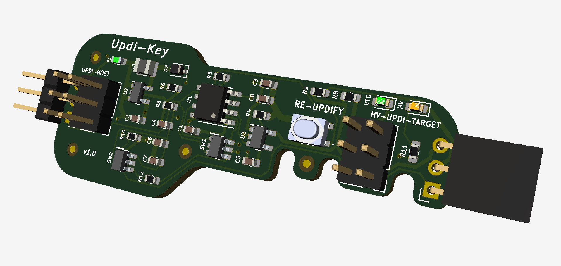
Updi-Key is an inline adapter that transforms your favorite UPDI programmer into a HV UPDI programmer. Now you can easily enable UPDI mode, program and power-cycle your target MCU to explore additional features like using the UPDI pin for LUT0, AIN0, GPIO or Reset.
To provide a tool that allows easy access to the additional functions of the programming pin, which becomes more important in low pin count applications. To enhance your existing programming solution with a convenient low cost adapter.
Unique, versatile, easy to use with the existing programming environment you're already familiar with.
| Item | Qty | Reference | Manufacturer Number | Digi-Key Part Number | Description |
|---|---|---|---|---|---|
| 1 | 3 | C1, C7, C8 | CL10B104KB8NNNC | 1276-1000-1-ND | CAP CER 0.1UF 50V X7R 0603 |
| 2 | 1 | C6 | CL10A475KO8NNNC | 1276-1784-1-ND | CAP CER 4.7UF 16V X5R 0603 |
| 3 | 1 | D2 | PMEG4005CEJX | 1727-8169-1-ND | DIODE SCHOTTKY 40V 500MA SC90 |
| 4 | 2 | R8, R9 | RK73B1JTTD102J | 2019-K73B1JTTD102JCT-ND | RES 1K OHM 5% 1/8W 0603 |
| 5 | 3 | R3, R4, R10 | RK73B1JTTD103J | 2019-RK73B1JTTD103JCT-ND | RES 10K OHM 5% 1/10W 0603 |
| 6 | 2 | R11, R12 | RK73B1JTTD181J | 2019-RK73B1JTTD181JCT-ND | RES 180 OHM 5% 1/8W 0603 |
| 7 | 1 | SW1 | SN74LVC1G3157DBVR | 296-14908-1-ND | IC SWITCH SPDT SOT23-6 |
| 8 | 1 | R6 | RC0603FR-0711KL | 311-11.0KHRCT-ND | RES SMD 11K OHM 1% 1/10W 0603 |
| 9 | 1 | R5 | RC0603FR-07102KL | 311-102KHRCT-ND | RES SMD 102K OHM 1% 1/10W 0603 |
| 10 | 1 | C4 | CC0603BRNPO9BNR68 | 311-3842-1-ND | CAP CER 0.68PF 50V NPO 0603 |
| 11 | 1 | VTG1 | LG Q396-PS-35 | 475-3754-1-ND | LED GREEN DIFFUSED 0603 SMD |
| 12 | 1 | F1 | 0ZCM0005FF2G | 507-1816-1-ND | PTC RESET FUSE 15V 50MA 0603 |
| 13 | 1 | U3 | MIC2091-1YM5-TR | 576-3891-1-ND | MICROCHIP - MIC2091-1YM5-TR - POWER SWITCH, 100MA, SOT23-5 |
| 14 | 1 | L1 | CBC2518T470K | 587-3060-1-ND | FIXED IND 47UH 290MA 2.47 OHM |
| 15 | 3 | C2, C3, C5 | LMK107BBJ106MALT | 587-3258-1-ND | CAP CER 10UF 10V X5R 0603 |
| 16 | 1 | HV1 | APTD1608SECK/J4-PF | 754-1802-1-ND | LED ORANGE CLEAR 0603 (1608 Metric) |
| 17 | 1 | U1 | ATTINY202-SSNR | ATTINY202-SSNRCT-ND | IC MCU 8BIT 2KB FLASH 8SOIC |
| 18 | 1 | SW3 | PTS810SJG250SMTRLFS | CKN10504CT-ND | SWITCH TACTILE SPST-NO 0.05A 16V |
| 19 | 1 | SW2 | ISL43210IHZ-T | ISL43210IHZCT-ND | IC SWITCH SPDT SOT23-6, Marking GJQG |
| 20 | 1 | U2 | NCP1406SNT1G | NCP1406SNT1GOSCT-ND | IC REG BUCK BST ADJ 25MA 5TSOP |
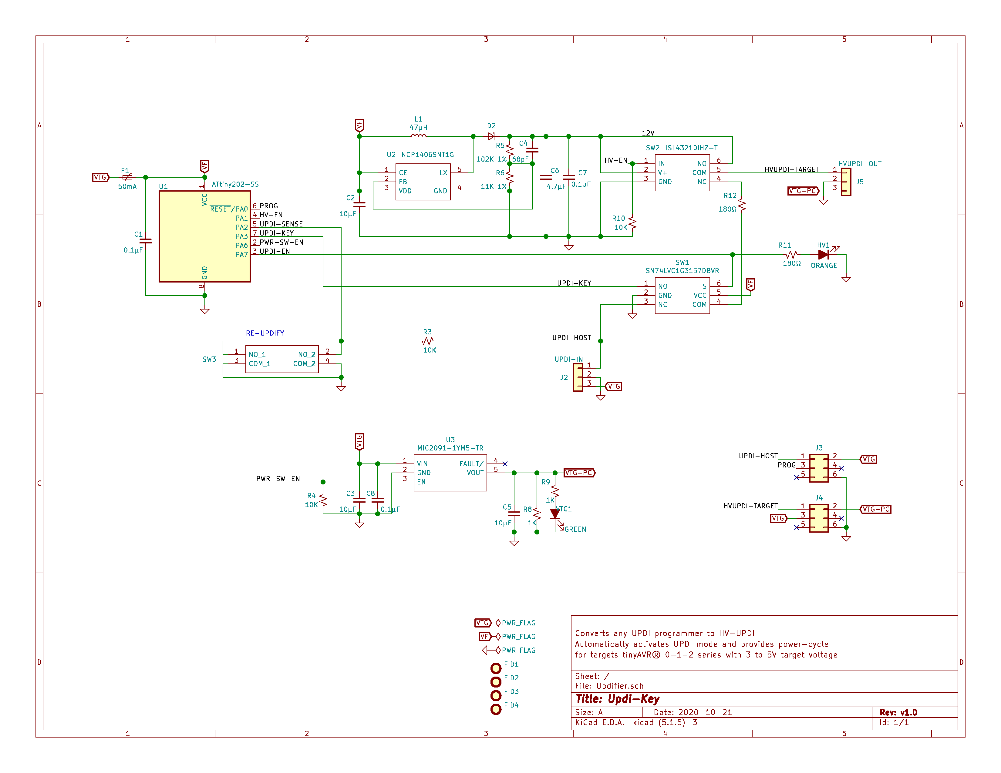
Connect a UPDI programmer to J3 (Pin2 VTG to VCC, Pin3 PROG to UPDI, Pin6 to GND)
Install the latest version of megaTinyCore
Install the Updi-Key Firmware
● Click on the green "Clone or download" button, then select "Download ZIP".
● Unzip this file in a folder on your PC.
● In the Arduino IDE, open the sketch "UpdiKey.ino" in the "source\updikey" folder
● Use these board settings:
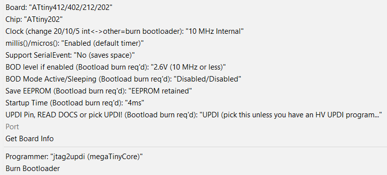
● Select "Burn Bootloader" then "Upload Using Programmer" from the Arduino IDE. Updi-Key is now ready to use.
High Voltage Programming Options
| Mode | Description |
|---|---|
| Simple High Voltage Pulse | On power-up, Updi-Key safely transfers onto the UPDI signal and applies the 12V pulse, triggers low to initiate the enable sequence then sends the SYNC character and the NVMPROG key, then switches the signal back to the host programmer. The target's PA0 pin remains in UPDI mode as long as power remains on. For additional programming sessions, pressing the Re-updify button is not required. Any changes to the fuses will get loaded on the next power-up. |
| Auto Power Cycle High Voltage Pulse | On power-up, the target's PA0 pin is changed to UPDI mode as described above. After programming, an automatic power-cycle will occur and any new fuse settings will take effect. If re-programming is required, press the Re-updify button first. This power-cycles and sends the HV pulse and enable sequence to re-activate UPDI mode. |
UPDI Host Pin Description
| Pin | Name | Type | Description |
|---|---|---|---|
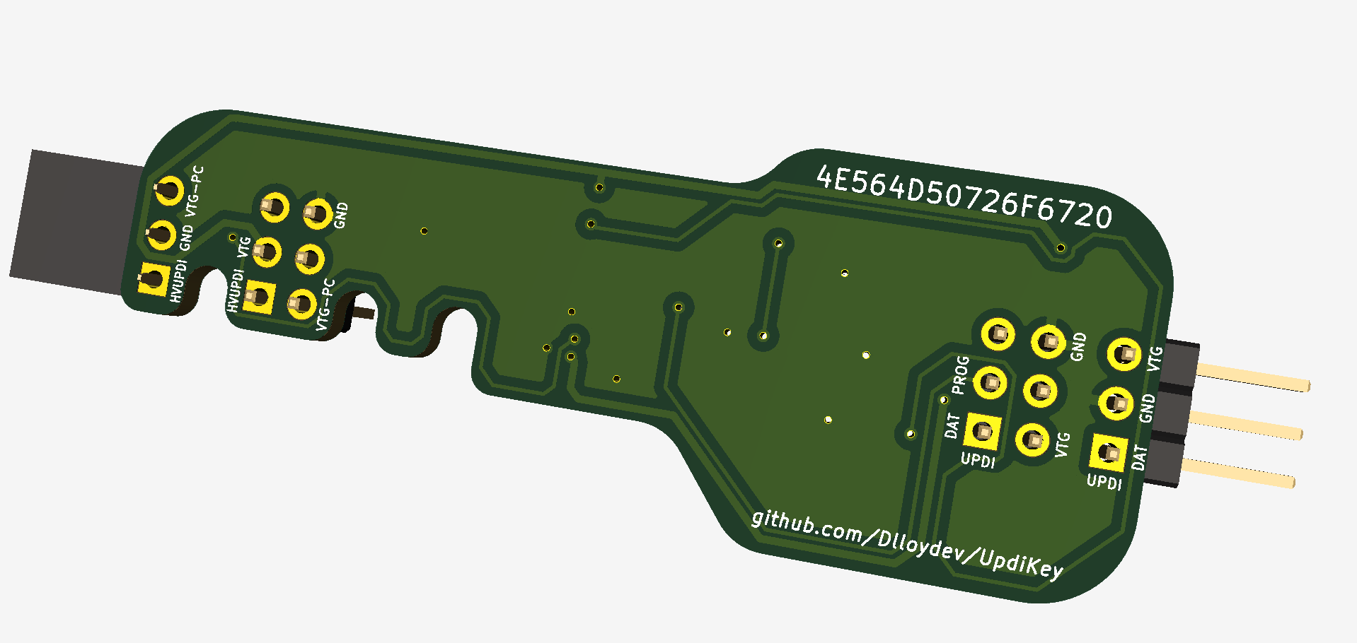
| J2-1 | UPDI-HOST | I/O | UPDI signal from programmer |
| J2-2 | GND | Power | Ground |
| J2-3 | VTG | Power | Target voltage supply (3-5V) |
| J3-1 | UPDI-HOST | I/O | UPDI signal from programmer |
| J3-2 | VTG | Power | Target voltage supply (3-5V) |
| J3-3 | PROG | I/O | Updi-Key UPDI programming pin |
| J3-6 | GND | Power | Ground |
UPDI Target Pin Description
| Pin | Name | Type | Description |
|---|---|---|---|
| J5-1 | HVUPDI-TARGET | I/O | HVUPDI signal to target |
| J5-2 | GND | Power | Ground |
| J5-3 | VTG-PC | Power | Target voltage supply (3-5V) with Power Cycle and 100mA current limiting |
| J4-1 | HVUPDI-TARGET | I/O | HVUPDI signal to target |
| J4-2 | VTG-PC | Power | Target voltage supply (3-5V) with Power Cycle and 100mA current limiting |
| J4-3 | VTG | I/O | Target voltage supply (3-5V) |
| J4-6 | GND | Power | Ground |
Green VTG LED:
This LED is connected to VTG-PC so it will be both power on indication and power-cycle indication.
Orange HV LED:
On power-up or just after the Re-Updify button is released, the orange HV LED will be on during the HV pulse and enable sequence.
Target Power:
VTG-PC: This pin is the output of the MIC2091 power switch that is optimized for 100mA over-current limiting and circuit protection.
VTG: This pin connects directly to your external power source.
Re-Updify:
This button is used just prior to re-programming when using "Auto Power Cycle and High Voltage Pulse" mode.
| Qty | Value | Footprint | References |
|---|---|---|---|
| 4 | Fiducial | Fiducial:Fiducial_1mm_Mask2mm | FID1, FID2, FID3, FID4 |
| 3 | 0.1µF | Capacitor_SMD:C_0603_1608Metric | C1, C7, C8 |
| 3 | 10K | Resistor_SMD:R_0603_1608Metric | R3, R4, R10 |
| 3 | 10µF | Capacitor_SMD:C_0603_1608Metric | C2, C3, C5 |
| 2 | 180Ω | Resistor_SMD:R_0603_1608Metric | R11, R12 |
| 2 | 1K | Resistor_SMD:R_0603_1608Metric | R8, R9 |
| 1 | 102K 1% | Resistor_SMD:R_0603_1608Metric | R5 |
| 1 | 11K 1% | Resistor_SMD:R_0603_1608Metric | R6 |
| 1 | 4.7µF | Capacitor_SMD:C_0603_1608Metric | C6 |
| 1 | 47µH | Inductor_SMD:L_1008_2520Metric | L1 |
| 1 | 50mA | Fuse:Fuse_0603_1608Metric | F1 |
| 1 | 68pF | Capacitor_SMD:C_0603_1608Metric | C4 |
| 1 | ATtiny202-SS | Package_SO:SOIC-8_3.9x4.9mm_P1.27mm | U1 |
| 1 | GREEN | LED_SMD:LED_0603_1608Metric | VTG1 |
| 1 | HVUPDI-OUT | Connector_PinSocket_2.54mm:PinSocket_1x03_P2.54mm_Horizontal | J5 |
| 1 | HVUPDI_OUT6 | Connector_PinHeader_2.54mm:PinHeader_2x03_P2.54mm_Vertical | J4 |
| 1 | ISL43210IHZ-T | 0_mouser:SOT95P280X145-6N | SW2 |
| 1 | MIC2091-1YM5-TR | 0_mouser:SOT95P280X130-5N | U3 |
| 1 | NCP1406SNT1G | 0_mouser:SOT95P275X110-5N | U2 |
| 1 | ORANGE | LED_SMD:LED_0603_1608Metric | HV1 |
| 1 | PMEG4005CEJX | Diode_SMD:D_SOD-323F | D2 |
| 1 | PTS810SJG250SMTRLFS | 0_mouser:PTS810SJG250SMTRLFS | SW3 |
| 1 | SN74LVC1G3157DBVR | 0_mouser:SOT95P280X145-6N | SW1 |
| 1 | UPDI-IN | Connector_PinHeader_2.54mm:PinHeader_1x03_P2.54mm_Horizontal | J2 |
| 1 | UPDI_IN6 | Connector_PinHeader_2.54mm:PinHeader_2x03_P2.54mm_Vertical | J3 |
It measures 56.5 × 22.2 mm and has 2 copper layers, 1.6 mm thick.
36 parts, built around the ATTINY202-SSN, MIC2091-1YM5-TR, ISL43210IHZ-T and PMEG4005CEJX. The full list of its parts is on this page, with links to each part's symbol and footprint where PCBKit's library has them.
From the Dlloydev/Updi-Key repository on GitHub, at the commit this page was made from: the board is KiCad/Updifier/Updifier.kicad_pcb. PCBKit opens the board in the browser, with nothing to install.
Its repository publishes it under the MIT licence: you may reuse it on that licence's terms (keep the author's notice, and for a copyleft licence share your changes alike).

stanleyondrus/ILDAWaveX16
ILDAWaveX16 is an open-source, high-resolution, wireless laser DAC with SD-card playback, network control, and ILDA output.


fsodari/USBAudioBridge
NXP RT1010 based USB to I2S bridge to connect to a Digilent Arty A7.

justinjchae/poko
Poko: a phone-free MagSafe companion. nRF52840 + Zephyr, round display, haptic ring, voice memos, iPhone app, parametric CAD, KiCad.

MunyratanakBrorn/Smart-Electrical-Energy-Management-System
Bachelor of Technology Thesis Project 2024.

Pollex/MFM-Module-RS485
A MultiFlexMeter (MFM) sensor module. The hardware is a generic carrier: RS-485 + 1-Wire, with a software-selectable sensor supply rail (3.6 V / 5 V / 12 V).