
2 layers116.8 × 154.9 mm

 djtersteegc/rx02-emulator-mega-shield7
Arduino Mega2560 shield with buttons and LCD for AK6DN's DEC RX02 emulator code
Rx02-emulator mega shield is an open-source printed circuit board by djtersteegc, from the djtersteegc/rx02-emulator-mega-shield repository on GitHub, published under the MIT licence. It is a 2-layer board of 99.1 × 71.1 mm with 58 parts on 101 nets, routed with 333 tracks and 0 vias.
It is built around the 74HCT14D. Its parts include 26 resistors, 8 connectors, 7 transistors, 5 capacitors and 4 switches. It belongs with the lEDs and displays boards of this library.
Arduino Mega2560 shield with buttons and LCD based on AK6DN's DEC RX02 emulator board design and code. There is a fork of his project at https://github.com/djtersteegc/rx02_emulator that adds software support for the new board design.
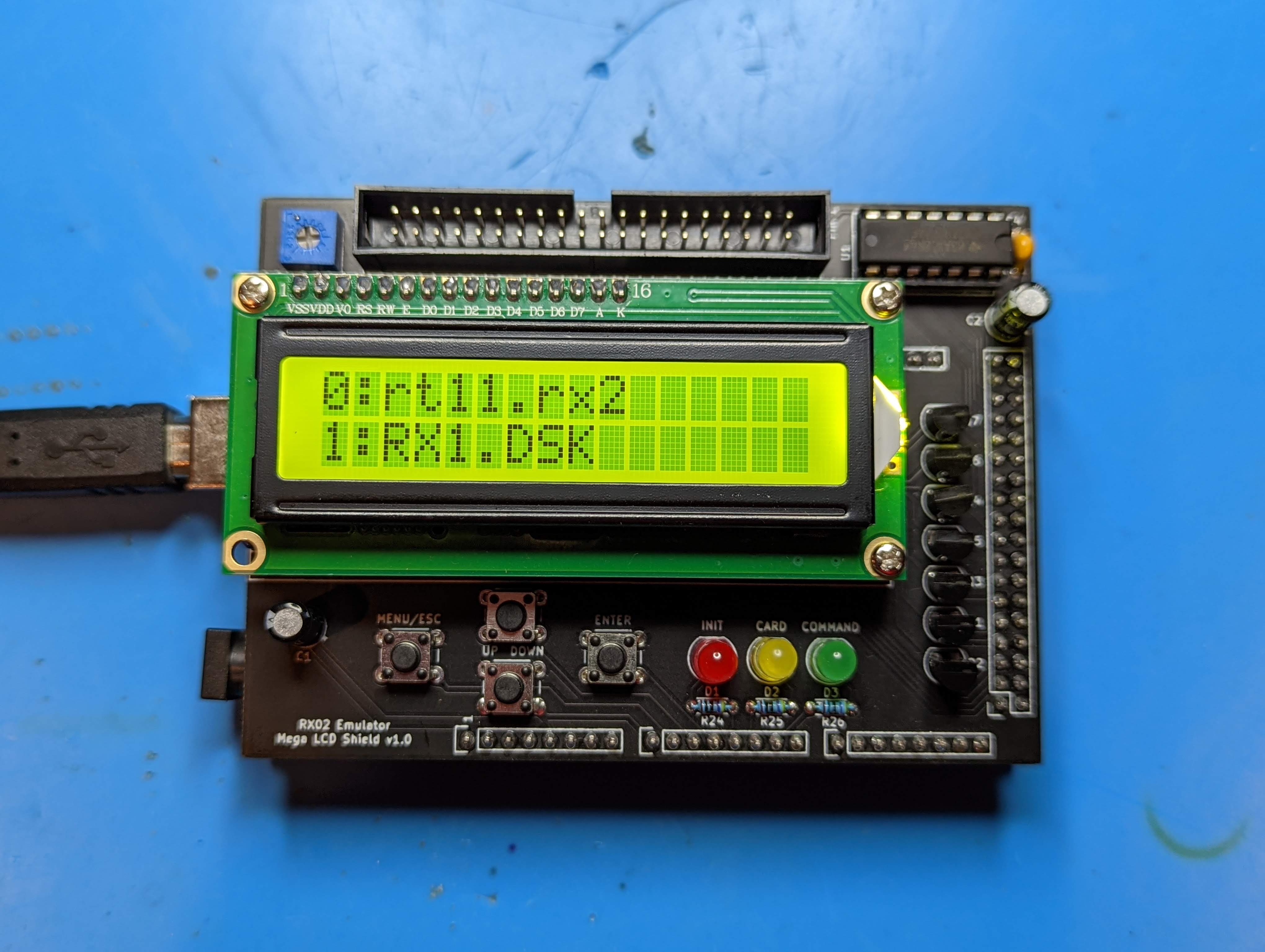
You can also still run it via the original serial terminal command scheme. If you don't want to build it with the LCD or buttons, you can disable supprort in the code by leaving
#define USE_LCD_MENU
commented out (undefined) in my_project.h
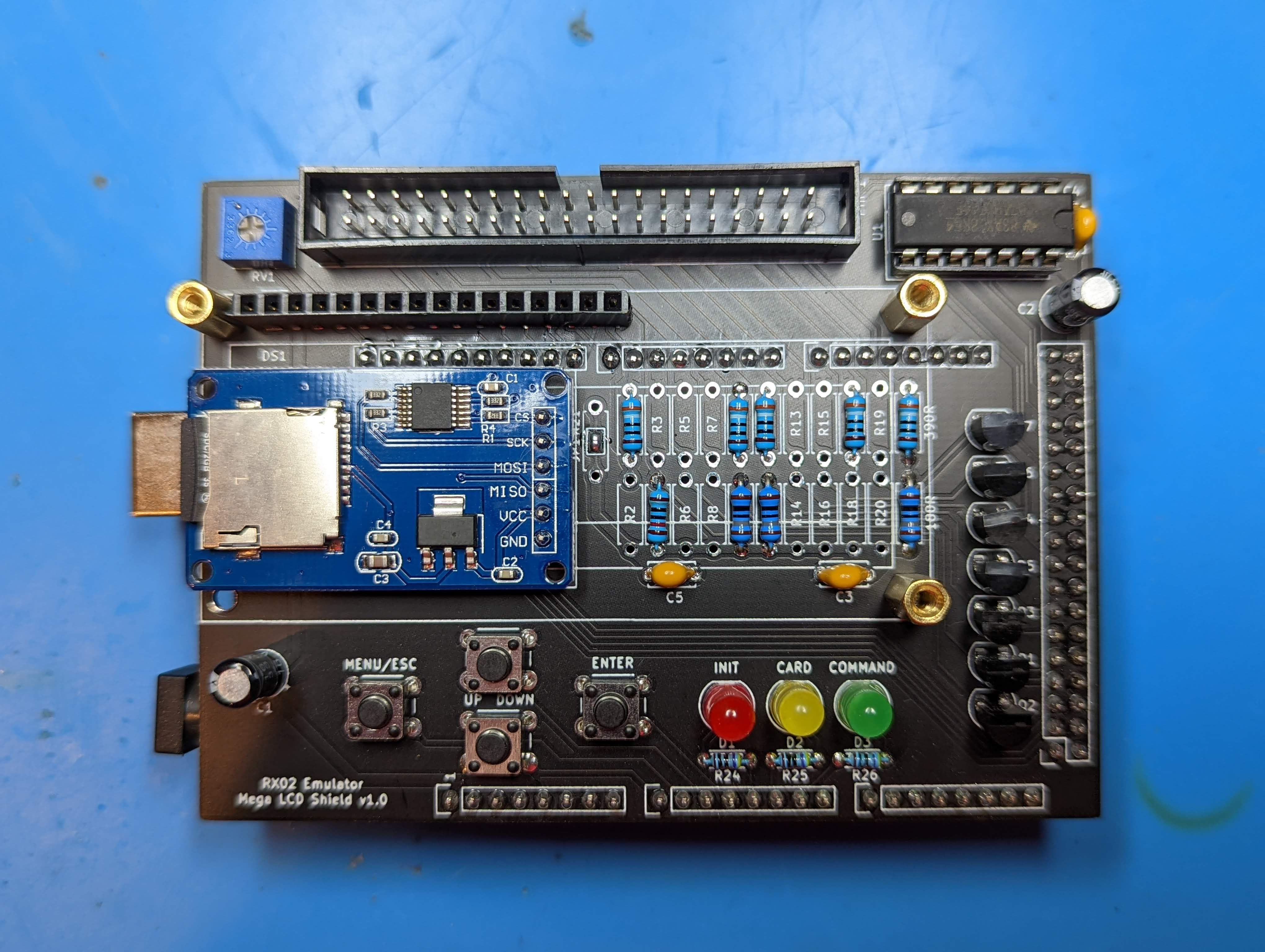
Resistor numbers is also different than AK6DN's original board so please refer to this mapping table below or the CSV file.
Termination Resistor Table.csv
Most of the resistor footprints should NOT be populated.
| Signal | Resistor | Value | Resistor | Value |
|---|---|---|---|---|
| RX_DMA_MODE_H | R2 | - | R1 | 390 |
| RX_AC_L | R4 | 120 | R3 | - |
| RX_OUT_L | R6 | - | R5 | - |
| RX_SHIFT_L | R8 | - | R7 | - |
| RX_12BIT_L | R10 | 180 | R9 | 390 |
| RX_DATA_L | R12 | 180 | R11 | 390 |
| RX_DONE_L | R14 | - | R13 | - |
| RX_XFER_RQST_L | R16 | - | R15 | - |
| RX_INIT_L | R18 | - | R17 | 390 |
| RX_ERROR_L | R20 | - | R19 | - |
| RX_RUN_L | R23 | 180 | R22 | 390 |
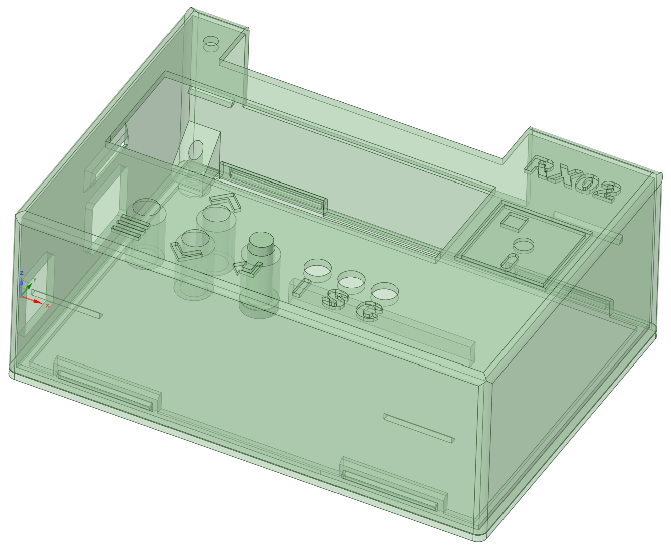
STL's and the DesignSpark Mechanical source file for an snap fit enclosure are in the enclosure directory. There is also a provision to secure it with one M3x6mm (or longer) screw if you want. Since the power and USB port spacing on the Chinese clone Arduino Mega2560's with the CH340 serial chip is different than the original design there are two STL's for the case body, pick the one that matches your board.
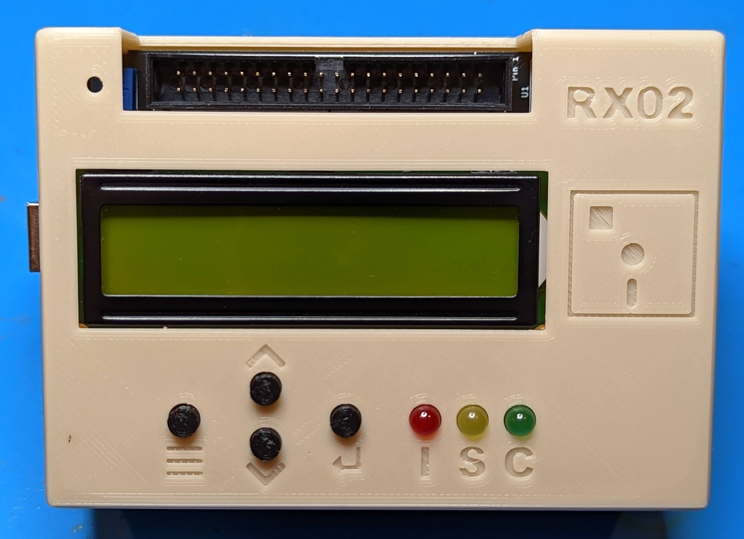
All components can be sourced from the usual low cost China based vendors for a total build cost of around $20. Please see the assembly page for more details.
Hardware Component Choices and Assembly
An interactive BOM and parts placement diagram is also available.
Interactive Bill of Materials (BOM)
You can download the Gerbers and use your favorite fab (JLCPCB, PCBWay, etc.) to make your own batch. It's a standard two layer, 1oz copper board with dimensions of 99mm x 71mm so it squeaks under the 100mm x 100mm limit of the cheap Chinese fabs.
After designing and building the Mega Pro SMD version of this, I discovered the reason you always had to do a ReINIT of the emulator to get it recognized was I failed to pick interrupt enabled pins on the Mega2560 for the RX_INIT and RX_RUN lines. This has been corrected in the v1.1 board and you can fix this yourself in v1.0 by adding two jumper wires from D22 to D2, and D26 to D3. Once complete, reflash with the updated version of the code at https://github.com/djtersteegc/rx02_emulator
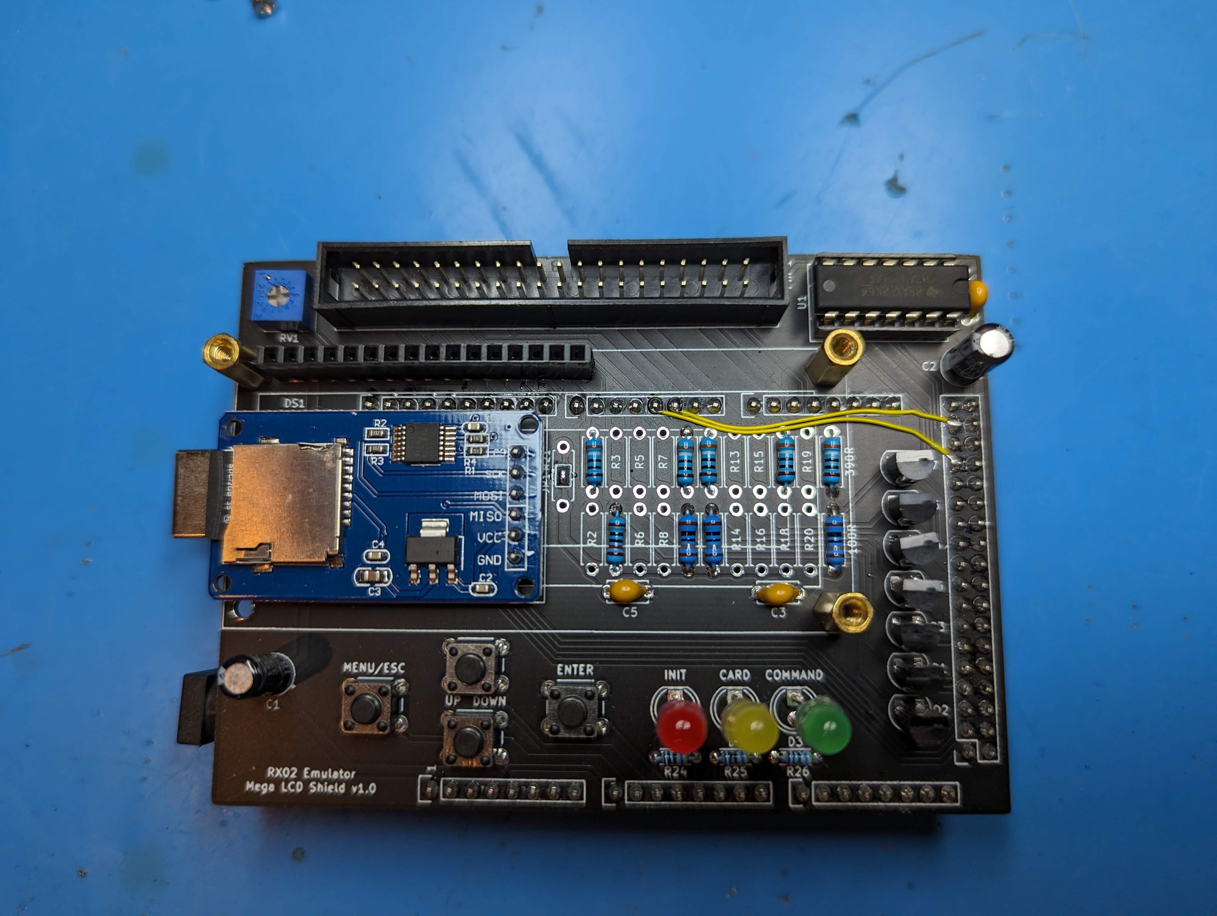
Moved the RX_INIT and RX_RUN lines to interrupt enabled pins on the Mega2560.
| Qty | Value | Footprint | References |
|---|---|---|---|
| 11 | 180R | Resistor_THT:R_Axial_DIN0207_L6.3mm_D2.5mm_P7.62mm_Horizontal | R2, R4, R6, R8, R10, R12, R14, R16, R18, R20, R23 |
| 11 | 390R | Resistor_THT:R_Axial_DIN0207_L6.3mm_D2.5mm_P7.62mm_Horizontal | R1, R3, R5, R7, R9, R11, R13, R15, R17, R19, R22 |
| 7 | 2N7000 | Package_TO_SOT_THT:TO-92_HandSolder | Q1, Q2, Q3, Q4, Q5, Q6, Q7 |
| 3 | 0.1uf | Capacitor_THT:C_Disc_D5.0mm_W2.5mm_P5.00mm | C3, C4, C5 |
| 3 | 330R | Resistor_THT:R_Axial_DIN0204_L3.6mm_D1.6mm_P5.08mm_Horizontal | R24, R25, R26 |
| 2 | 33uf | Capacitor_THT:CP_Radial_D5.0mm_P2.50mm | C1, C2 |
| 2 | Analog | Socket_Arduino_Mega:Socket_Strip_Arduino_1x08 | P3, P4 |
| 1 | 100R | Resistor_THT:R_Axial_DIN0207_L6.3mm_D2.5mm_P7.62mm_Horizontal | R21 |
| 1 | 10K | 3362P-1-103:TRIM_3362P-1-103 | RV1 |
| 1 | 74HCT14 | Package_DIP:DIP-14_W7.62mm_Socket_LongPads | U1 |
| 1 | CARD | LED_THT:LED_D5.0mm | D2 |
| 1 | CARD-SD-ADAPTER-CATALEX | CARD-SD-ADAPTER-CATALEX:Catalex-MicroSD-Card-Up-No-Holes | MOD1 |
| 1 | COMMAND | LED_THT:LED_D5.0mm | D3 |
| 1 | Communication | Socket_Arduino_Mega:Socket_Strip_Arduino_1x08 | P7 |
| 1 | Conn_02x20_Odd_Even | Connector_IDC:IDC-Header_2x20_P2.54mm_Vertical | J1 |
| 1 | DOWN | Button_Switch_THT:SW_PUSH_6mm_H4.3mm | SW2 |
| 1 | Digital | Socket_Arduino_Mega:Socket_Strip_Arduino_2x18 | P1 |
| 1 | ENTER | Button_Switch_THT:SW_PUSH_6mm_H4.3mm | SW4 |
| 1 | INIT | LED_THT:LED_D5.0mm | D1 |
| 1 | MENU/ESC | Button_Switch_THT:SW_PUSH_6mm_H4.3mm | SW1 |
| 1 | PWM | Socket_Arduino_Mega:Socket_Strip_Arduino_1x08 | P6 |
| 1 | PWM | Socket_Arduino_Mega:Socket_Strip_Arduino_1x10 | P5 |
| 1 | Power | Socket_Arduino_Mega:Socket_Strip_Arduino_1x08 | P2 |
| 1 | SolderJumper_2_Open | Jumper:SolderJumper-2_P1.3mm_Open_TrianglePad1.0x1.5mm | JP1 |
| 1 | UP | Button_Switch_THT:SW_PUSH_6mm_H4.3mm | SW3 |
| 1 | WC1602A | Display:WC1602A | DS1 |

gmcn42/clumsyMIDI
A THT-only Raspberry Pi expansion board containing a MIDI interface, DAC, and OLED display

schlae/snark-barker-mca
A Sound Blaster compatible sound card for Micro Channel bus computers


RobertPHeller/RPi-RRCircuits
A collection of circuit designs for various MCUs, not just Raspberry Pis relating to Model Railroading


hkzlab/TurboXT_Addon
8Mhz Turbo / Reset addon board for the IBM 5160 (The original XT)
It measures 99.1 × 71.1 mm and has 2 copper layers, 1.6 mm thick.
58 parts, built around the 74HCT14D. The full list of its parts is on this page, with links to each part's symbol and footprint where PCBKit's library has them.
From the djtersteegc/rx02-emulator-mega-shield repository on GitHub, at the commit this page was made from: the board is rx02-emulator-mega-shield.kicad_pcb. PCBKit opens the board in the browser, with nothing to install.
Its repository publishes it under the MIT licence: you may reuse it on that licence's terms (keep the author's notice, and for a copyleft licence share your changes alike).