2 layers80 × 30 mm
SS3-Power
diorcety/SS3
DIY Weller WMRP / WMRT / WXUP soldering station — transformer-based, MSPM0G1507 MCU, 4× dual N-MOSFET triac stage, 7-seg or 1.9" TFT display. Inspired by kair.us/projects/weller.
54 parts

 diorcety/SS3
DIY Weller WMRP / WMRT / WXUP soldering station — transformer-based, MSPM0G1507 MCU, 4× dual N-MOSFET triac stage, 7-seg or 1.9" TFT display. Inspired by kair.us/projects/weller.
SS3-Display is an open-source printed circuit board by diorcety, from the diorcety/SS3 repository on GitHub. It is a 2-layer board of 80 × 30 mm with 88 parts on 94 nets, routed with 822 tracks and 276 vias.
It is built around the 74HC595, MCP6V02-E/MD and TDCR1050M, with the TPS7A2033PDBVR-TP, BAT854SW and PEC12R-4022F-S0024 among its other parts. Its parts include 47 resistors, 15 capacitors, 6 ICs, 4 connectors and 1 diode. It belongs with the lEDs and displays boards of this library.


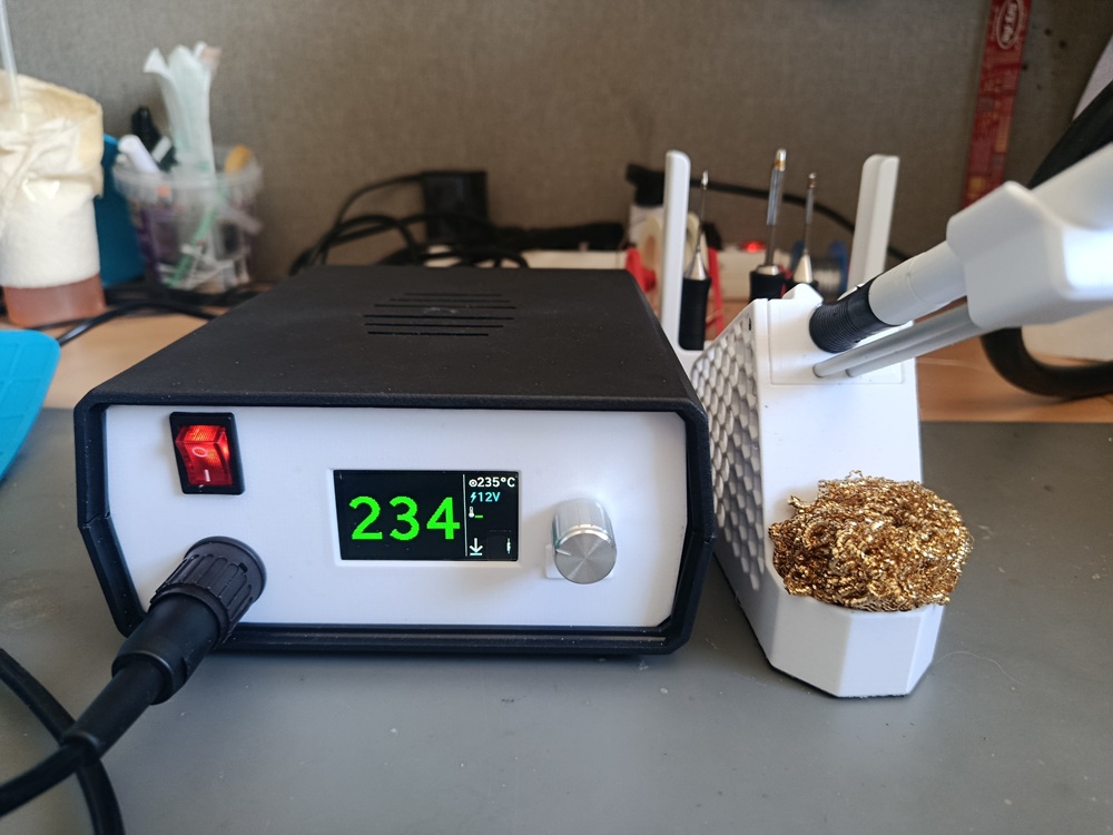
A DIY Weller-compatible soldering station controller, inspired by the kair.us Weller WMRP and WMRT compatible soldering station.
SS3 is a two-board redesign of the kair.us open-source solder station. The key differences from the original are:
Handles all control logic, ADC measurements, and user interface.
device_linker.cmdDrives the resistive heating element of the tip.
Compatible with Weller active tips using an integrated heater and thermocouple:
SS3/
├── 3D/       — Stands and handle models (12V and 24V variants; no enclosure provided)
├── PCBS/     — KiCad / Gerber files for both boards, plus KiCad conversions of the
│              original kair.us WMRP and WMRT boards (including mirrored variant for
│              mirrored jack barrels)
├── SIMS/     — LTSpice simulations: zero-cross detection, 3.6V SMPS from half-wave
│              rectifier, and back-to-back N-MOSFET triac equivalent
└── SS3/ — Firmware source (CMake project)Based on the open-source Weller WMRP and WMRT compatible soldering station by kair.us.
| Qty | Value | Footprint | References |
|---|---|---|---|
| 9 | 33 | Resistor_SMD:R_0402_1005Metric | R21, R22, R23, R24, R25, R26, R27, R28, R29 |
| 8 | 0 | Resistor_SMD:R_0402_1005Metric | R9, R10, R11, R12, R13, R15, R16, R49 |
| 8 | 1k/0.1% | Resistor_SMD:R_0402_1005Metric | R1, R2, R3, R4, R35, R36, R40, R41 |
| 8 | TestPoint | TestPoint:TestPoint_THTPad_D2.0mm_Drill1.0mm | TP1, TP2, TP3, TP4, TP5, TP6, TP7, TP8 |
| 6 | MountingHole | Project:MountingHole_2mm_M1.8_Pad | H1, H2, H3, H4, H5, H6 |
| 5 | 196 | Resistor_SMD:R_0402_1005Metric | R44, R45, R46, R47, R48 |
| 5 | 1u | Capacitor_SMD:C_0402_1005Metric | C1, C3, C4, C12, C15 |
| 4 | 100n | Capacitor_SMD:C_0402_1005Metric | C2, C7, C13, C14 |
| 4 | 1k | Resistor_SMD:R_0402_1005Metric | R30, R31, R32, R33 |
| 4 | 340 | Resistor_SMD:R_0402_1005Metric | R14, R17, R18, R19 |
| 3 | 249n | Capacitor_SMD:C_0402_1005Metric | C9, C10, C11 |
| 2 | 10k | Resistor_SMD:R_0402_1005Metric | R42, R43 |
| 2 | 17.8k/0.1% | Resistor_SMD:R_0402_1005Metric | R38, R39 |
| 2 | 300k/0.1% | Resistor_SMD:R_0402_1005Metric | R5, R6 |
| 2 | 4.7k | Resistor_SMD:R_0402_1005Metric | R7, R8 |
| 2 | 74HC595 | Package_SO:TSSOP-16_4.4x5mm_P0.65mm | U4, U5 |
| 1 | 0.47u | Capacitor_SMD:C_0402_1005Metric | C8 |
| 1 | 10n | Capacitor_SMD:C_0402_1005Metric | C5 |
| 1 | 10u | Capacitor_SMD:C_0603_1608Metric | C6 |
| 1 | 47k | Resistor_SMD:R_0402_1005Metric | R20 |
| 1 | BAT854SW | Package_TO_SOT_SMD:SOT-323_SC-70 | D1 |
| 1 | Conn_02x10 | Project:BF100-20-A-D-1-0640 | J3 |
| 1 | I2C | Connector_PinHeader_2.54mm:PinHeader_1x04_P2.54mm_Vertical | J1 |
| 1 | MCP6V02 | Package_SO:SOIC-8_3.9x4.9mm_P1.27mm | U1 |
| 1 | MSPM0G1506SRHBR | Package_DFN_QFN:VQFN-32-1EP_5x5mm_P0.5mm_EP3.5x3.5mm_ThermalVias | U3 |
| 1 | PEC12R-4022F-S0024 | Project:PEC12R-4022F-S0024 | S1 |
| 1 | SPI | Connector_PinHeader_2.54mm:PinHeader_1x08_P2.54mm_Vertical | J2 |
| 1 | SWD | Project:20021511-00010T4LF | J4 |
| 1 | TDCR1050M | Project:TDCR1050M | U6 |
| 1 | TPS7A2033PDBVR | Package_TO_SOT_SMD:SOT-23-5 | U2 |
It measures 80 × 30 mm and has 2 copper layers, 1.6 mm thick.
88 parts, built around the 74HC595, MCP6V02-E/MD, TDCR1050M and TPS7A2033PDBVR-TP. The full list of its parts is on this page, with links to each part's symbol and footprint where PCBKit's library has them.
From the diorcety/SS3 repository on GitHub, at the commit this page was made from: the board is PCBS/SS3/SS3-Display.kicad_pcb and its schematic PCBS/SS3/7SEG.kicad_sch. PCBKit opens the board in the browser, with nothing to install.
Its repository states no licence, so its author keeps all rights: ask diorcety before reusing the design.
diorcety/SS3
DIY Weller WMRP / WMRT / WXUP soldering station — transformer-based, MSPM0G1507 MCU, 4× dual N-MOSFET triac stage, 7-seg or 1.9" TFT display. Inspired by kair.us/projects/weller.

diorcety/SS3
DIY Weller WMRP / WMRT / WXUP soldering station — transformer-based, MSPM0G1507 MCU, 4× dual N-MOSFET triac stage, 7-seg or 1.9" TFT display. Inspired by kair.us/projects/weller.

diorcety/SS3
DIY Weller WMRP / WMRT / WXUP soldering station — transformer-based, MSPM0G1507 MCU, 4× dual N-MOSFET triac stage, 7-seg or 1.9" TFT display. Inspired by kair.us/projects/weller.


Solvro/hardware-wakacyjne-wyzwanie-2025
Ścieżka Hardware to część interdyscyplinarnego projektu edukacyjnego Wakacyjne Wyzwanie Solvro 2025, który ma na celu wprowadzenie studentów w świat elektroniki i jej programowania.


znibb/ThreeMan_HW
According to Hardware Semantic Versioning (MAJOR.MINOR.PATCH), increment: MAJOR - when changing mechanical or connector interfaces MINOR - when changing schematic or layout PATCH - when changing BOM or sourcing data


UzixLS/zxevo1010-board
10x10cm PCB variant of ZX-Evolution project for G738/G706 enclosure