
2 layers80 × 30 mm
SS3-Display
diorcety/SS3
DIY Weller WMRP / WMRT / WXUP soldering station — transformer-based, MSPM0G1507 MCU, 4× dual N-MOSFET triac stage, 7-seg or 1.9" TFT display. Inspired by kair.us/projects/weller.
88 parts

 diorcety/SS3
DIY Weller WMRP / WMRT / WXUP soldering station — transformer-based, MSPM0G1507 MCU, 4× dual N-MOSFET triac stage, 7-seg or 1.9" TFT display. Inspired by kair.us/projects/weller.
Wmrt handle is an open-source printed circuit board by diorcety, from the diorcety/SS3 repository on GitHub. It is a 2-layer board of 22 × 9.5 mm with 12 parts on 8 nets, routed with 31 tracks and 0 vias.
It is built around the KTY82/110 and RI80SMDM-0510-J1. Its parts include 3 resistors, 1 switch and 1 crystal.
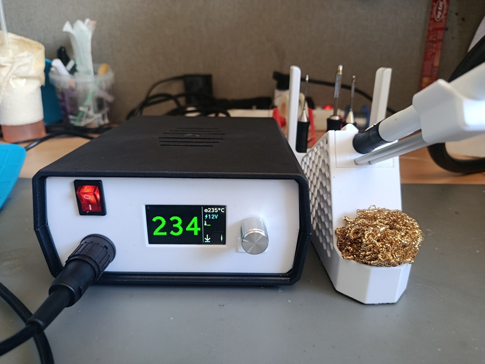
A DIY Weller-compatible soldering station controller, inspired by the kair.us Weller WMRP and WMRT compatible soldering station.
SS3 is a two-board redesign of the kair.us open-source solder station. The key differences from the original are:
Handles all control logic, ADC measurements, and user interface.
device_linker.cmdDrives the resistive heating element of the tip.
Compatible with Weller active tips using an integrated heater and thermocouple:
SS3/
├── 3D/       — Stands and handle models (12V and 24V variants; no enclosure provided)
├── PCBS/     — KiCad / Gerber files for both boards, plus KiCad conversions of the
│              original kair.us WMRP and WMRT boards (including mirrored variant for
│              mirrored jack barrels)
├── SIMS/     — LTSpice simulations: zero-cross detection, 3.6V SMPS from half-wave
│              rectifier, and back-to-back N-MOSFET triac equivalent
└── SS3/ — Firmware source (CMake project)Based on the open-source Weller WMRP and WMRT compatible soldering station by kair.us.
| Qty | Value | Footprint | References |
|---|---|---|---|
| 6 | TESTPOINTTH_1MM3_ROUND | wmrt_handle:P1-13-R | W1, W2, W4, W5, W6, W7 |
| 1 | 09-9792-20-05 | wmrt_handle:09-9792-20-05_BINDER | X1 |
| 1 | 0R | wmrt_handle:R0805 | R3 |
| 1 | 2k | wmrt_handle:R0805 | R1 |
| 1 | JAKA_LOGO_SILK_NANO | wmrt_handle:JAKA_SILK_NANO | U$1 |
| 1 | KTY82/110 | wmrt_handle:SOT-23 | R2 |
| 1 | RI80SMDM-0510-J1 | wmrt_handle:RI-80_SMDM_J-1 | S1 |
diorcety/SS3
DIY Weller WMRP / WMRT / WXUP soldering station — transformer-based, MSPM0G1507 MCU, 4× dual N-MOSFET triac stage, 7-seg or 1.9" TFT display. Inspired by kair.us/projects/weller.

diorcety/SS3
DIY Weller WMRP / WMRT / WXUP soldering station — transformer-based, MSPM0G1507 MCU, 4× dual N-MOSFET triac stage, 7-seg or 1.9" TFT display. Inspired by kair.us/projects/weller.

diorcety/SS3
DIY Weller WMRP / WMRT / WXUP soldering station — transformer-based, MSPM0G1507 MCU, 4× dual N-MOSFET triac stage, 7-seg or 1.9" TFT display. Inspired by kair.us/projects/weller.

github-linguist/linguist
Language Savant. If your repository's language is being reported incorrectly, send us a pull request!


google/mozc-devices
Circuit diagrams and firmware source code for Gboard DIY keyboards


hackclub/OnBoard
💡 Join 1,000 teenagers and make your first PCB with a $100 grant!

VoronDesign/Voron-Tap
Tap is a nozzle-based z-probe for the V2 and Trident printer designs. The entire toolhead moves to trigger an optical switch. Tap offers many advantages:

stacksmashing/pico-tpmsniffer
A simple, very experimental TPM sniffer for LPC bus
It measures 22 × 9.5 mm and has 2 copper layers, 1.6 mm thick.
12 parts, built around the KTY82/110 and RI80SMDM-0510-J1. The full list of its parts is on this page, with links to each part's symbol and footprint where PCBKit's library has them.
From the diorcety/SS3 repository on GitHub, at the commit this page was made from: the board is PCBS/wmrt_handle/wmrt_handle.kicad_pcb and its schematic PCBS/SS3/7SEG.kicad_sch. PCBKit opens the board in the browser, with nothing to install.
Its repository states no licence, so its author keeps all rights: ask diorcety before reusing the design.