2 layers80 × 30 mm
SS3-Display
diorcety/SS3
DIY Weller WMRP / WMRT / WXUP soldering station — transformer-based, MSPM0G1507 MCU, 4× dual N-MOSFET triac stage, 7-seg or 1.9" TFT display. Inspired by kair.us/projects/weller.
88 parts

 diorcety/SS3
DIY Weller WMRP / WMRT / WXUP soldering station — transformer-based, MSPM0G1507 MCU, 4× dual N-MOSFET triac stage, 7-seg or 1.9" TFT display. Inspired by kair.us/projects/weller.
Handle V2 is an open-source printed circuit board by diorcety, from the diorcety/SS3 repository on GitHub. It is a 2-layer board of 40 × 7 mm with 12 parts on 6 nets, routed with 28 tracks and 2 vias.
Its parts include 3 resistors and 1 switch.
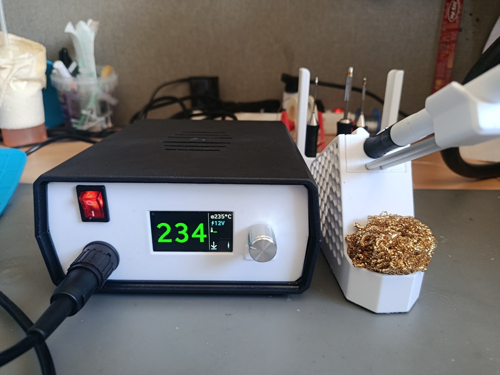
A DIY Weller-compatible soldering station controller, inspired by the kair.us Weller WMRP and WMRT compatible soldering station.
SS3 is a two-board redesign of the kair.us open-source solder station. The key differences from the original are:
Handles all control logic, ADC measurements, and user interface.
device_linker.cmdDrives the resistive heating element of the tip.
Compatible with Weller active tips using an integrated heater and thermocouple:
SS3/
├── 3D/       — Stands and handle models (12V and 24V variants; no enclosure provided)
├── PCBS/     — KiCad / Gerber files for both boards, plus KiCad conversions of the
│              original kair.us WMRP and WMRT boards (including mirrored variant for
│              mirrored jack barrels)
├── SIMS/     — LTSpice simulations: zero-cross detection, 3.6V SMPS from half-wave
│              rectifier, and back-to-back N-MOSFET triac equivalent
└── SS3/ — Firmware source (CMake project)Based on the open-source Weller WMRP and WMRT compatible soldering station by kair.us.
| Qty | Value | Footprint | References |
|---|---|---|---|
| 5 | WIREPADSMD5-1,8 | handle-V2:5-1,8 | GND0, HT0, RING0, SLEEVE0, TIP0 |
| 3 | handle-V2:SMD1,27-2,54 | ESD0, PTY0, SW0 | |
| 1 | 0 | handle-V2:R0805 | R2 |
| 1 | 1k | handle-V2:R0805 | R1 |
| 1 | KTY82 | handle-V2:R0805 | R3 |
| 1 | REED_SWITCH-PTH-INSULATED | handle-V2:REED_SWITCH_PLASTIC | S1 |
diorcety/SS3
DIY Weller WMRP / WMRT / WXUP soldering station — transformer-based, MSPM0G1507 MCU, 4× dual N-MOSFET triac stage, 7-seg or 1.9" TFT display. Inspired by kair.us/projects/weller.

diorcety/SS3
DIY Weller WMRP / WMRT / WXUP soldering station — transformer-based, MSPM0G1507 MCU, 4× dual N-MOSFET triac stage, 7-seg or 1.9" TFT display. Inspired by kair.us/projects/weller.

diorcety/SS3
DIY Weller WMRP / WMRT / WXUP soldering station — transformer-based, MSPM0G1507 MCU, 4× dual N-MOSFET triac stage, 7-seg or 1.9" TFT display. Inspired by kair.us/projects/weller.

github-linguist/linguist
Language Savant. If your repository's language is being reported incorrectly, send us a pull request!


google/mozc-devices
Circuit diagrams and firmware source code for Gboard DIY keyboards


hackclub/OnBoard
💡 Join 1,000 teenagers and make your first PCB with a $100 grant!

VoronDesign/Voron-Tap
Tap is a nozzle-based z-probe for the V2 and Trident printer designs. The entire toolhead moves to trigger an optical switch. Tap offers many advantages:

stacksmashing/pico-tpmsniffer
A simple, very experimental TPM sniffer for LPC bus
It measures 40 × 7 mm and has 2 copper layers, 0.8 mm thick.
12 parts. The full list of its parts is on this page, with links to each part's symbol and footprint where PCBKit's library has them.
From the diorcety/SS3 repository on GitHub, at the commit this page was made from: the board is PCBS/handle/handle-V2.kicad_pcb and its schematic PCBS/SS3/7SEG.kicad_sch. PCBKit opens the board in the browser, with nothing to install.
Its repository states no licence, so its author keeps all rights: ask diorcety before reusing the design.