4 layers50 × 50 mm
Load
AresEnsea/2324_Projet2A_AresCFR
Ce repository GitHub regroupe l'ensemble des projets & documents réalisés par l'association Ares pour la Coupe de France de Robotique 2024 – Farming Mars.
56 parts7
 diminDDL/PicoLasDriver1
This repository houses the necessary components for a touchscreen-based controller/driver for the Picolas series of laser diode boards, including hardware schematics, embedded firmware, and a Python GUI.
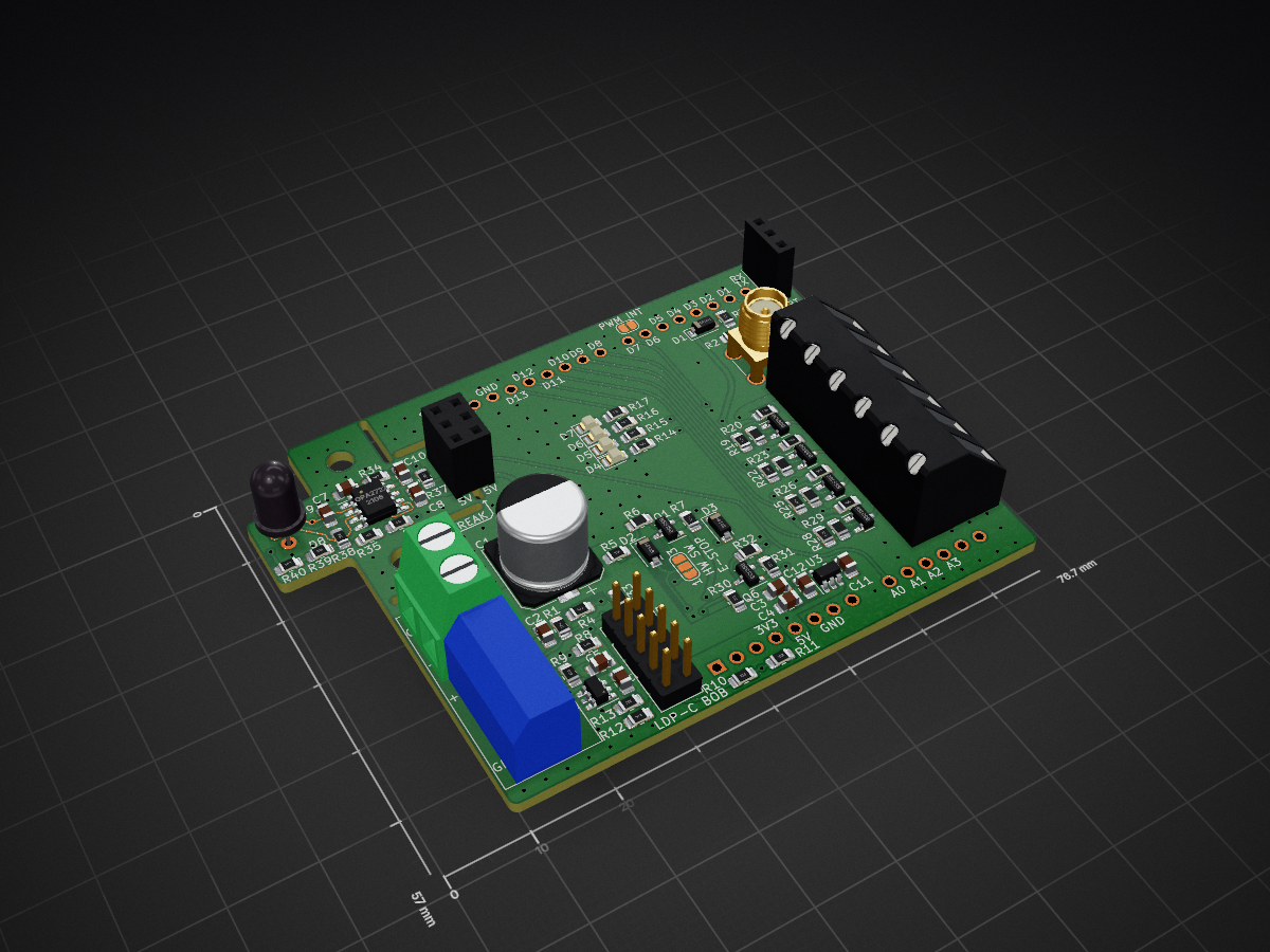
Shield is an open-source printed circuit board by diminDDL, from the diminDDL/PicoLasDriver repository on GitHub, published under the MIT licence. It is a 2-layer board of 76.7 × 57 mm with 82 parts on 59 nets, routed with 377 tracks and 201 vias.
It is built around the ARDUINO UNO R3, OPA2727AID and MIC5205-3.3YM5, with the BSS138 among its other parts. Its parts include 40 resistors, 12 capacitors, 8 diodes, 7 connectors and 6 transistors. It belongs with the AVR (ATmega, ATtiny) boards of this library.


This repository houses the necessary components for a touchscreen-based controller/driver for the Picolas series of laser diode boards, including hardware schematics, embedded firmware, and a Python GUI.

⚠️ Important: It is recommended to turn off the output when adjusting settings to prevent potential glitches on the output.


The board keeps the Picolas driver's enable pin high and uses the trigger pin to generate impulses. An analog DAC sets the voltage to control the output current limit. If the E-STOP pin is triggered, the system becomes non-functional until a power cycle.
This project is licensed under the MIT License.
| Qty | Value | Footprint | References |
|---|---|---|---|
| 21 | 10k | Resistor_SMD:R_0805_2012Metric_Pad1.20x1.40mm_HandSolder | R1, R10, R11, R18, R19, R21, R22, R24, R25, R27, R28, R30, R31, R34, R38, R39 +5 |
| 8 | 1k | Resistor_SMD:R_0805_2012Metric_Pad1.20x1.40mm_HandSolder | R3, R4, R12, R13, R14, R15, R16, R17 |
| 7 | N.P. | Resistor_SMD:R_0805_2012Metric_Pad1.20x1.40mm_HandSolder | R6, R20, R23, R26, R29, R32, R33 |
| 6 | BSS138 | Package_TO_SOT_SMD:SOT-23 | Q1, Q2, Q3, Q4, Q5, Q6 |
| 5 | 10u | Capacitor_SMD:C_0805_2012Metric_Pad1.18x1.45mm_HandSolder | C2, C3, C5, C8, C12 |
| 4 | 100n | Capacitor_SMD:C_0805_2012Metric_Pad1.18x1.45mm_HandSolder | C4, C6, C7, C10 |
| 3 | 1N4148 | Diode_SMD:D_SOD-123 | D1, D2, D3 |
| 2 | 100 | Resistor_SMD:R_0805_2012Metric_Pad1.20x1.40mm_HandSolder | R35, R36 |
| 2 | 50 | Resistor_SMD:R_0805_2012Metric_Pad1.20x1.40mm_HandSolder | R2, R37 |
| 2 | INTR | Jumper:SolderJumper-2_P1.3mm_Bridged2Bar_RoundedPad1.0x1.5mm | JP2, JP3 |
| 2 | MountingHole | MountingHole:MountingHole_3.2mm_M3 | H1, H2 |
| 1 | 1000u | Capacitor_SMD:CP_Elec_10x10 | C1 |
| 1 | 3p | Capacitor_SMD:C_0805_2012Metric_Pad1.18x1.45mm_HandSolder | C9 |
| 1 | 470p | Capacitor_SMD:C_0805_2012Metric_Pad1.18x1.45mm_HandSolder | C11 |
| 1 | Arduino_UNO_R3 | Module:Arduino_UNO_R3 | A1 |
| 1 | BREAK | Connector_PinSocket_2.54mm:PinSocket_2x03_P2.54mm_Vertical | J7 |
| 1 | E-STOP | TerminalBlock:TerminalBlock_Altech_AK300-3_P5.00mm | J2 |
| 1 | ERR | LED_SMD:LED_0805_2012Metric_Pad1.15x1.40mm_HandSolder | D5 |
| 1 | HW E-STOP | Jumper:SolderJumper-3_P1.3mm_Bridged12_RoundedPad1.0x1.5mm_NumberLabels | JP1 |
| 1 | IO | TerminalBlock_Altech:Altech_AK300_1x06_P5.00mm_45-Degree | J4 |
| 1 | LDP-C BOB | Connector_PinHeader_2.54mm:PinHeader_2x05_P2.54mm_Vertical | J5 |
| 1 | LED | LED_SMD:LED_0805_2012Metric_Pad1.15x1.40mm_HandSolder | D7 |
| 1 | MCP4725xxx-xCH | Package_TO_SOT_SMD:SOT-23-6 | U1 |
| 1 | MIC5205-3.3YM5 | Package_TO_SOT_SMD:SOT-23-5 | U3 |
| 1 | OPA2727 | Package_SO:SO-8_3.9x4.9mm_P1.27mm | U2 |
| 1 | OUT_EN | LED_SMD:LED_0805_2012Metric_Pad1.15x1.40mm_HandSolder | D4 |
| 1 | SFH 213 | LED_THT:LED_D5.0mm_IRGrey | D8 |
| 1 | TRG | Connector_Coaxial:SMA_Amphenol_901-144_Vertical | J1 |
| 1 | TRGR'D | LED_SMD:LED_0805_2012Metric_Pad1.15x1.40mm_HandSolder | D6 |
| 1 | UART | Connector_PinSocket_2.54mm:PinSocket_1x03_P2.54mm_Vertical | J3 |
| 1 | VIN | TerminalBlock:TerminalBlock_Altech_AK300-2_P5.00mm | J6 |
It measures 76.7 × 57 mm and has 2 copper layers, 1.6 mm thick.
82 parts, built around the ARDUINO UNO R3, OPA2727AID, MIC5205-3.3YM5 and BSS138. The full list of its parts is on this page, with links to each part's symbol and footprint where PCBKit's library has them.
From the diminDDL/PicoLasDriver repository on GitHub, at the commit this page was made from: the board is HW/shield/shield.kicad_pcb and its schematic HW/shield/shield.kicad_sch. PCBKit opens the board in the browser, with nothing to install.
Its repository publishes it under the MIT licence: you may reuse it on that licence's terms (keep the author's notice, and for a copyleft licence share your changes alike).
AresEnsea/2324_Projet2A_AresCFR
Ce repository GitHub regroupe l'ensemble des projets & documents réalisés par l'association Ares pour la Coupe de France de Robotique 2024 – Farming Mars.

gk977246/Openmower_Brushed
I have rebuilt a Bosch Indego800. It had no RPMSensor on the mowing motor, so i added magnet and hallsensor myself. It is easily possible, to convert any old mower with brushed motors, to openmower with RTK.

PineConeMechatronics/EUPLA_CONE_CORE
Academic hardware development for the EUPLA_CONE_CORE project, including manufacturing files and sensor testing scripts.

johntheseegler/janus_tasks
task1atm1 is the ardiomo code for implementing moving average.

cbiffle/keybrain
Drop-in replacement controller for WASD CODE v2B keyboard


microdynamics-robot-quadcopter/breeze_electronics_design
This project is created and managed by EDA softwares, which contains the breeze quadcopter's component library, footprint library, schematic, printed circuit boards, etc.